-
-
January 30, 2019 at 6:14 pm
Colleen
SubscriberHello,
I need to make a wheel rotate to satisfy a boundary condition in my model. I have a frictionless contact region between the axle and the wheel, but can't seem to make the correct contact region between the wheel and the floor correct to make the wheel rotate on the surface.Â
Could you please advise me if this is possible?
Thanks!
Â
Â
-
January 30, 2019 at 7:18 pm
peteroznewman
SubscriberColleen,
What is the question you want the model to answer? Depending on the question, different models will provide appropriate answers.
For example, a turbine disk holds turbine blades and spins at a very high rotational velocity. A Static Structural analysis of a sector of the disk and one blade has the center of the disk as a fixed support, and a rotational velocity applied to all the bodies. The rotational velocity BC creates the centrifugal force on the mass pulling it outward.
You are showing a wheel in contact with a surface in a Static Structural model and say the wheel has a frictionless connection to the axle. I assume you want the wheel to roll on the surface. In this context, the Rotational Velocity is inappropriate for this model and should be deleted. You could make the surface move to the left or the wheel axle move to the right. The results in Static Structural would be the same. It's a little simpler to make the surface move to the left, so also delete the Fixed Support. It might be good to make the surface a little longer in the X axis.
Here is what to add:
- Translational Joint along the X axis between the surface and ground. (Joints are under Connections).
- Joint load for the translational joint of a -4 mm displacement. This moves the surface to the left so the wheel will roll.
- Frictional contact between the wheel and the surface.
- Bonded Contact between the wheels and the axle
- Revolute Joint between the axle and the arm so the wheels can spin.
- Spherical Joint between the right end of the arm and ground (like a trailer hitch).
- Add Standard Earth Gravity -Y direction so the wheel can have a force against the surface.
- Make this a 2-step Analysis.
- Turn Auto Time Stepping On.
- Step 1, the Joint Displacement = 0. Just let Gravity set the wheels down on the surface.
- Step 2, let the Joint Displacement = -4 mm.
- Make Step 2 have Initial Substeps of 20 and Minimum Substeps of 20 to get 20 frames of the wheel rolling.
- Turn on Large Displacements.
 Let me know if that works for you.
Regards, Peter
-
January 31, 2019 at 6:58 pm
Colleen
SubscriberHi Peter,
The part I’m looking at is actually part of a larger wheelchair frame model. Originally, I didn’t model any wheels and had frictionless boundary conditions at the wheel locations. However, I was finding that the model was overconstrained because it didn’t allow for any rotation, and it wasn’t matching my physical validation model, which I’m doing using with strain gauges. So I am hoping that by inputting wheels into the model, I can allow for both rotation and forward translation when a downwards load is applied to the chair.
I’m working through the steps you’ve provided. A couple questions.. When I create a joint, do I need to delete the contact between those two bodies? I’ve created a two-step analysis in Analysis Settings. How do I input the loads into different steps in a multi-step analysis? With the standard earth gravity, do I apply that load to all bodies? I would think it would make sense to not apply it to the floor, but I can’t see how to select individual bodies.
Thank you for your help!
-
January 31, 2019 at 7:10 pm
peteroznewman
SubscriberHi Colleen,
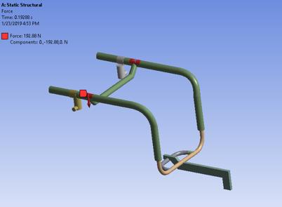
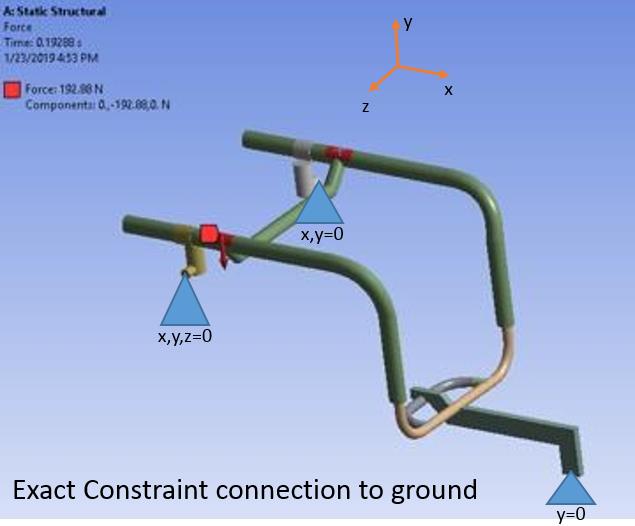
If you are interested in the stress on a wheelchair frame, you might not need wheels or a ground surface to do that. You could create a Remote Displacement scoped to the part of the frame where the wheel connects to the frame and make the remote point at the center of the axle. Since there are two wheels on the ground sharing a common axle, are you assuming the axle has some clearance so the arm can rock between the two wheels freely for a few degrees? If so, that is the point to put the remote point. The Remote Displacement can provide just one constraint, y=0 so everything else is free on two of the "wheels". If you have four wheels, you will have to make one remote displacement have x,y,z = 0 to anchor the frame to a point, while another remote displacement separated along the x axis from the first "wheel" will have y,z=0 to stop the wheelchair frame from spinning about the x,y,z=0 point.
Alternatively, if there is a very stiff and clearance-free connection of the axle to the arm, say through a pair of roller bearings, then you probably need two wheels on the ground surface so the pressure of each wheel to the ground can be different as the frame distorts under load.
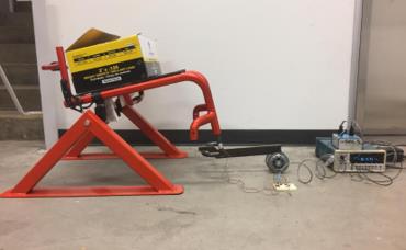
Let me know which case applies and reply with an image of the wheelchair frame and the loads you want to apply to it.
ANSWERS
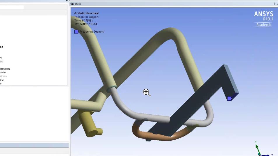
When you create a joint between two bodies, you don't also want contact between the same two bodies. Delete or suppress that.
Once you type Steps = 2 under Analysis Settings, every load in your model now gets two rows; one for step 1 and one for step 2. Type in the values you want to use on each row.
Gravity applies to all mass in the model. If you have a floor, gravity will pull that down too, but the translation joint will support that load as well as the wheel forces.
Regards, Peter
-
January 31, 2019 at 8:33 pm
Colleen
SubscriberThanks for your response. I think I'm looking at the second case. At the moment, I'm looking at a 1000N static downward load applied to the top of the wheelchair. I've attached a picture below of both my physical and my FEA model. However, I'm also planning to look at failures associated with fatigue, and will need to model the chair moving so that would be a different load case.Â
-
January 31, 2019 at 9:19 pm
-
January 31, 2019 at 11:26 pm
-
February 1, 2019 at 1:33 am
peteroznewman
SubscriberHi Colleen,
I deliberately have different constraints on one big wheel axle vs. the other wheel axle.
In your model, the X axis is along the cylindrical axis of the two axles. If you have two cylindrical supports along the same axis, then you need a constraint to prevent motion along that axis. That is why one of the two has x,y,z=0 constraint to stop motion along that axis.
I am suggesting a Remote Displacement on those cylindrical faces that leaves rotations free. This is more realistically representing how the axles are free to rotate given they have a big wheel mounted to the axle.
I am also suggesting a Remote Displacement on the face where you show a Frictionless Support on the end of the trailing arm. The Fritionless Support is holding that face flat and not allowing Y displacement but also not allowing rotation about X or Z. By replacing the Frictionless Support with a Remote Displacement that only has Y=0 and leaves all other DOF free, the frame will be free to distort in a realistic way.
-
July 19, 2019 at 11:16 am
nihe
SubscriberHi Peter,
i read your first answer and ich want to simulate a wheel like a turbine disk. I can apply the velocity easily, but i am struggling with the supports. Can you also help me with that?
Â
Best regards
-
July 19, 2019 at 11:52 am
peteroznewman
SubscriberNihe, please create a New Discussion and copy/paste the text in the post above into that New Discussion, then delete the post above.
The reason is this Discussion is owned by Colleen and you will not be notified of any replies. This Discussion is also marked as Solved.
-
July 19, 2019 at 12:08 pm
nihe
Subscriber Hello Peter,
Â
thanks for the reply. New Discussion is created.
Â
Â
-
- The topic ‘Making a Wheel Rotate in Ansys Static Structural’ is closed to new replies.
- LPBF Simulation of dissimilar materials in ANSYS mechanical (Thermal Transient)
- Convergence error in modal analysis
- APDL, memory, solid
- Meaning of the error
- How to model a bimodular material in Mechanical
- Simulate a fan on the end of shaft
- Real Life Example of a non-symmetric eigenvalue problem
- Nonlinear load cases combinations
- How can the results of Pressures and Motions for all elements be obtained?
- Contact stiffness too big
-
4167
-
1487
-
1338
-
1188
-
1021
© 2025 Copyright ANSYS, Inc. All rights reserved.


