-
-
April 21, 2020 at 1:35 pm
bamdadslr
SubscriberHi all,
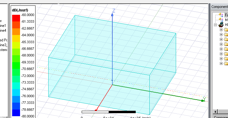
I am trying to excite two series transmission lines using a Lumped port in HFSS (As in the attached picture). So, there are two cylindrical conductors (transmission lines) on the two sides of a lumped port above PEC ground. The lines are open at their end. To avoid reflections, I want to use FE-BI on the air box around the structure. When I set this up, it gives me an error of "Solving frequency...(Domain solver), process hf3d error: Failure in solving the ports...Please contact Ansys technical support ". I would appreciate any help in this regard.
Even without considering the bottom face of air region as PEC (assigning all faces as FE-BI), it gives the same error.
Thanks.
-
April 28, 2020 at 6:24 pm
rtk
Ansys EmployeeHello,
As per the explanation given above for the model creation I couldn't find any issues with the simulation (without PEC ground). Just make sure couple of things below
1. Check for the proper defining of FE-BI Boundary. The assignment should come under Project Manager
2. I can see two Lumped RLC components in the attached figure. Validate those components. Where are they placed on the transmission line?
3. Make sure you have enabled 'solve inside' for the FE-BI region and that not needed for transmission lines.
Regards
-
May 11, 2020 at 6:19 pm
bamdadslr
SubscriberHello,
Thank you so much for your time and help. I could solve the error when I subtracted the transmission lines from the air region. Not sure how it solved the problem though.
I have another question. I want to simulate very long transmission lines in the mentioned configuration. So, to avoid increasing the simulation time, I want to use a small air box around the port, which includes a small part of the Tlines as well. Applying FEBI on the surface of the air box, and assigning Tlines that extend out of the box as IE regions. PEC boundary condition (infinite ground) is also applied to the bottom face of the air region. The simulation runs in this set up, but the results dont seem to be right. Is there anything wrong with the set up? because I have read that the current is continuous from FEM to IE region, so I think there is no problem in defining long Tlines in this way.
Please find the picture attached,
Thanks,
Bamdad
-
May 15, 2020 at 1:56 am
bamdadslr
SubscriberAny help would be appreciated.
-
May 15, 2020 at 7:53 am
rtk
Ansys EmployeeHello Bamdad,
The best way to create a long transmission line in HFSS is to utilize the Deembedding feature in its Excitation. An example workflow below.

For more information about modeling long transmission lines, see the Applications for Deembedding section in the Assign Excitation chapter in the HFSS online help document.
Regards,
-
May 15, 2020 at 1:02 pm
bamdadslr
SubscriberHello rtk,
Thank you for your idea. Its a nice way of modelling a long transmission line. The reason I like to use FEBI is that the general idea is to model 2 poles (towers) located at a distance of say 400m away from each other (simulation frequency between 100 kHz to 10 MHz), and a transmission line conductor is attached between them. So, to save the time and memory, I want to somehow put a small box of air around the two poles instead of modeling both in one big air box. This requires the Tline conductor to come out of the box1 (around tower 1), continues the current and enters box2 (around tower 2). This is the general purpose that made me think about the design that I sent a picture of.
I would appreciate if you could kindly provide guidelines on modeling with FEBI.
Regards,
-
May 20, 2020 at 4:30 am
bamdadslr
SubscriberAny help with the setup of FEBI is appreciated.
-
- The topic ‘Lumped port used in FE-BI’ is closed to new replies.


-
3597
-
1283
-
1107
-
1068
-
983

© 2025 Copyright ANSYS, Inc. All rights reserved.


