TAGGED: fdtd, FDTD-geometry, lumerical, Lumerical-FDTD, script
-
-
April 9, 2024 at 2:45 pm
minusunny
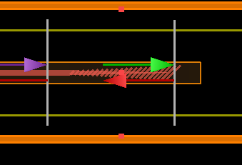
SubscriberI am trying to simulate tilted subwavelength gratings. I have few questions regarding the simulation,
- How do i place the input and output ports? The posted picture is XY view. Should i rotate ports with respect to the tilt angle?
- How do i place access input and output waveguides? Should i tilt them with respect to te SWG tilt?
This is my code to create SWG:
m = (wg_width-width_in)/taper_len; #Taper slope
b = width_in - (x0*m); #Taper width at x = 0
num_periods = floor(taper_len/period); #Number of SWG segments in the taper
period = period + (mod(taper_len,period)/num_periods); #Adjusts SWG period so there is an integer number of periods in the taper length
segment_width = dc*period*1; #Longitudinal thickness of SWG segments
x = x0 + (period/2); #Starting position
#x = -1*taper_len-0.5*period;
addstructuregroup;
set('name','swg1');
set('x',0e-06);
set('y',0e-06);
set('z',0e-6);
for(i = 1:num_periods) {
width = m*x + b; #Calculate taper width at current position
addrect;
set('name','seg_'+num2str(i));
set('material',coremat);
set('x',x); #Set x position based on current SWG segment
set('x span',segment_width); #Set longitudinal thickness based on SWG period and duty cycle
set('y',0e-06);
set('y span',width); #Set transverse width based on taper width at this x position
set('z min',-0.5*T);
set('z max',0.5*T); #Assuming 220 nm SOI platform
select('seg_'+num2str(i));
set('second axis','z');
set('rotation 2', -tilt);
addtogroup('swg1');
x = x + period; #Increment to next SWG segment
}
-
April 11, 2024 at 10:27 pm
Amrita Pati
Ansys EmployeeHi Minu,
I apologize for the delay in getting back to you. I wasn't sure about the setup and I thought I will discuss this internally before I respond to you. We don't think that EME will be a good choice to simulate this geometry. EME is typically used for geometries that support guided modes like waveguides, but it will be challenging to attain convergence in the SWG section. These gratings have a 3D mode distrubution, where as in EME when we only consider and match 2D modes that assume logitudinal invariance. Another point is that we don't advise users to simulate subwavelength geometries using EME. They also support a lot of evanescent modes that can be really hard to match at the interfaces. I will recommend using 3D FDTD and adding a transmission monitor on the grating side.
Regards,
Amrita -
April 11, 2024 at 10:29 pm
minusunny
SubscriberHi, thank you for your response. But i used FDTD simulation. How should i place the port in this case?
-
April 11, 2024 at 10:35 pm
Amrita Pati
Ansys EmployeeI apologize, I thought it was EME. On the output side, what are you planning to measure? I am asking because, I am curious if we even need ports. Do you just need the total transmission or some additional results?
Regards,
Amrita -
April 11, 2024 at 10:39 pm
minusunny
SubscriberI need to get the transmission. Can i set transmission port at an angle?
-
April 11, 2024 at 10:56 pm
Amrita Pati
Ansys EmployeeIf you just need to have the transmission, I will recommend using the monitor, instead of the ports at the output. Port is a combination of mode source, mode expansion monitor, and DFT monitor. It is useful when you want to find out what portion of the total transmission of is coupling to 2D guided modes at a given cross-section or if you are calculating S-paramters of PIC components. I don't think it will be useful here. You can simply use a transmission (Frequency domain field and power) monitor. Lumerical doesn't have an angled monitors. This article provides more information on the workaround: Creating curved and angled monitors. But let me get some second opinion on this and get back to you.
Regards,
Amrita -
April 11, 2024 at 10:57 pm
minusunny
SubscriberThat would be great , thanks
-
April 18, 2024 at 9:51 pm
Amrita Pati
Ansys EmployeeHi Minu,
I apologize for the delay, I spoke to my colleague. You should be able to use a regular DFT monitor for the transmission. You shouldn't have to rotate it to obtain the total transmission through the surface.
Regards,
Amrita
-
- The topic ‘Lumerical script and FDTD simulation ports’ is closed to new replies.


-
4838
-
1587
-
1386
-
1242
-
1021

© 2026 Copyright ANSYS, Inc. All rights reserved.


