-
-
March 5, 2024 at 5:25 am
Mohamed Selim
SubscriberFiber Model: https://optics.ansys.com/hc/en-us/articles/360036108194-Optical-Fiber-FIBER-INTERCONNECT-Element
I have a question regarding PMD effects on fiber model, in my simulation the chromatic dispersion is diabled (D=0 & S=0), fiber length 9 Km.
First: according to the model the user should enter differential group delay & PMD coeff.
However, according to the first reference in the model "“Nonlinear Fiber Optics", if I understand correctly then these two parameters are linked through the following equation:
It is not clear to me how to use the model using these two parameters at all, according to " Modeling and compensation of polarization effects in fiber-optic communication systems" the delay per each section in the fiber should be calculated directly using the D parameter and the section length, so why do we need an additional parameter as written in the link?
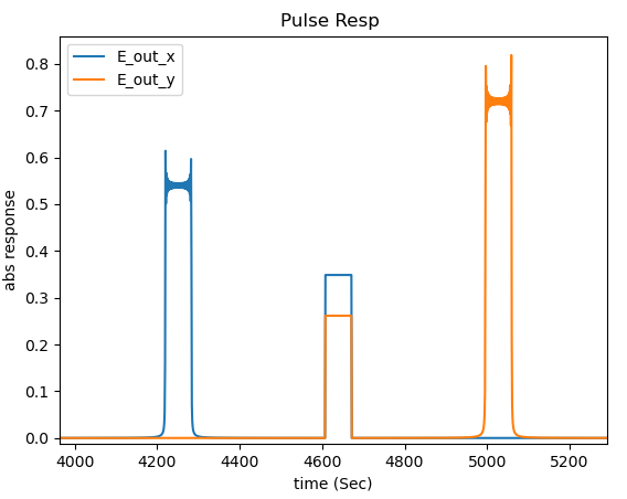
To illustrate my point, The following simulation is for a 9km length fiber and will make it two sections only (4.5km with zero sigma in length) using the following exaggerated numbers for differential group delay (3.3e-14) and pmd coefficient (3.3e-14) just for illustation, the following pulse response result (absolute electric field) is obtained at the output of the fiber:
I was expecting something different, at the output of the first section of the fiber, there should be two pulses (slow-axis and fast-axis pulses) each of these pulse will couple again into the second section producing the all combination ( slow-slow, fast-slow, fast-fast, slow-fast), so I was expecting something like this:
Please clarify these points to me.
Thanks -
March 14, 2024 at 3:54 am
GWANG
Ansys EmployeeHi Mohamed Selim,
Thank you for the post. I think you are right that you can define one of the parameters "differential group delay" and "pmd coefficient" to define the PMD dispersion. For the simulation result, could you please share with us your test file and I can help to take a look. Thank you.
-
March 14, 2024 at 4:03 am
Mohamed Selim
SubscriberHi Guanhui,
Thank you for the response, I don’t understand what do you mean by “I think you are right that you can define one of the parameters “differential group delay” and “pmd coefficient” to define the PMD dispersion”, the model requires both parameters to work and the results differ alot by defining one parameter only so the model seems to use both, while I think -based on the references I gave- the two parameters are closely linked to each other and are not independent.
It is not clear to me at all how to simulate the PMD effects of the fiber and the results don’t make sense to me as I told you so kindly clarify that point as it is very important for my research.
Which test file you mean? For lumerical setup I just use CW laser fed to an AM modulator that is excited by square pulse, very simple setup.
Other thing I forgot to mention, this equation written in the model’s link is wrong from dimensions point of view,
Because the dimension of Delta_Beta should be (s/m) while the dimension of the Dp parameter is Sec/sqrt(meter) (stated as ps/sqrt(km))
and that of L is meter. -
March 19, 2024 at 9:57 pm
GWANG
Ansys EmployeeHi Mohamed Selim,
Thank you for the feedback. I have elevated this up, and I got some comments from our R&D team:
- Equation 27 is wrong. I have updated the page and the length should have a sqrt. Here is the updated equation:

- The input parameter for PMD is the PMD coefficient, Dp, as in equation (26). Then the PMD differential group delay is calculated using eq (27). The differential group delay parameter is an user input additional delay that the user can use. Its not used in the delay calculated by equation 27 from PMD. You can see that its independent whether you enable PMD or not. More specificly, there are two differential group delays: One is the input parameter, this is an independent delay that the user can set whether PMD is enabled or not. There is another delay, not input parameter, that is calculated from the PMD coefficient as in eq 27 and is called deltaBetaPMD. Therefore you should only set the PMD coefficient and the PMD delay will be calculated according to eq(27). In addition you should set the differential group delay to 0.
Hope this now is clear.
- Equation 27 is wrong. I have updated the page and the length should have a sqrt. Here is the updated equation:
-
- The topic ‘Lumerical Interconnect Fiber PMD effects’ is closed to new replies.


-
4969
-
1645
-
1386
-
1242
-
1021

© 2026 Copyright ANSYS, Inc. All rights reserved.


