Hello,
I am trying to simulate the lasing of a nanotube (RI=4) in Lumerical FDTD,
I placed the plane source with a full range (400-800nm) or limited range (400-500 nm, 500-600 nm, 600-700 nm and 700-800 nm) at the begging of the tube. Then, put a DFTMonitor (Frequency-domain field and power) plane at the end of the nanotube. I also used lowQanalusis (analysis group) at the same place as the DFTMonitor,
I can understand the results, there are different results between the DFTMonitor and lowQanalusis analysis group
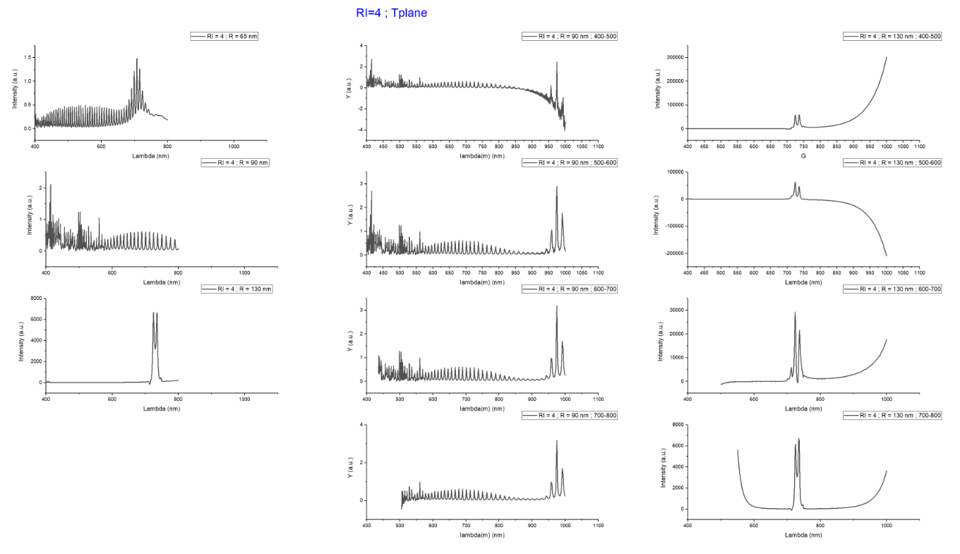
for DFTMonitor:
In a wide range: 400-800 nm wavelength, the spectra are full with peaks, and the number of peaks is reduced as the nanotube's radius is reduced (130 nm, 90 nm and 65 nm),
In a limited range (400-500 nm, 500-600 nm, 600-700 nm, and 700-800 nm):
For R= 65 nm, they are more peaks in the spectra compared to the full range, and the placed of the peaks are in the same places as the limited range increased,
For R= 130 nm, the same spectra compared to the full range and are the same as the limited range increased,
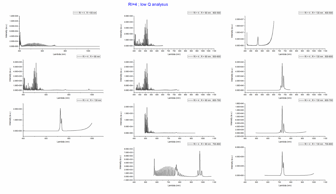
For lowQanalusis analysis group:
In a wide range: 400-800 nm wavelength, the number of peaks in the spectra are increased and then reduced as the nanotube's radius is reduced (130 nm, 90 nm and 65 nm),
In a limited range (400-500 nm, 500-600 nm, 600-700 nm and 700-800 nm):
For R= 65 nm, almost the same in a limited range (400-500 nm, 500-600 nm, 600-700 nm) but different for 700-800 nm limited range,
The are more peaks in the spectra compared to the full range, and the placed of the peaks are in the same places as the limited range increased,
For R= 130 nm, in the limited range (400-500 nm) only one peak and in a different place compared to the other limited range (500-600 nm, 600-700 nm, and 700-800 nm) that have two peaks.