TAGGED: transient-structural
-
-
October 10, 2023 at 11:55 am
Pedro Henrique de Melo Casado Matos
SubscriberHello everyone,
I am trying to perform a transient analysis of a cylindrical shell subject to a transient load in one end and fixed one the other. My goal is to see a pulse propagating along the pipe from the position of the load until the fixed end. This is the code I used to do the pre-processing:
""
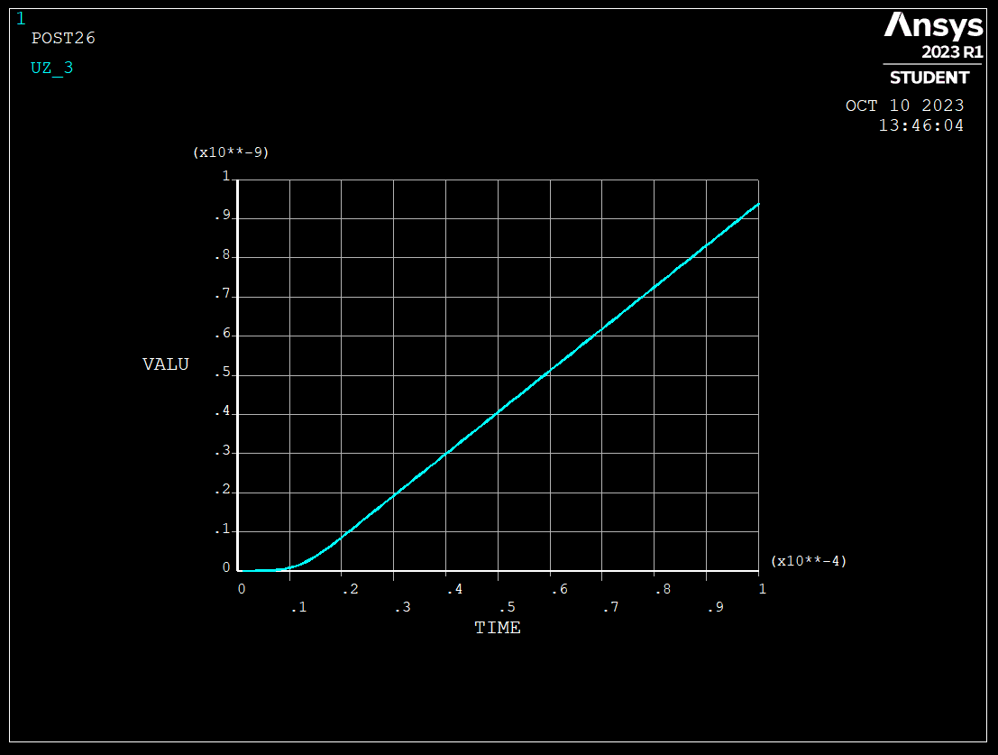
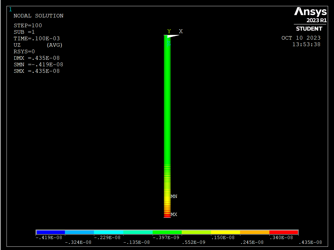
/CLEAR!Parameters*SET,diameter , 85.4*SET,thick , 11*SET,length , 100!Geometry/PREP7ET,1,SHELL181KEYOPT,1,8,2SECTYPE,1,SHELLSECDATA,thickMP,EX,1,2000MP,PRXY,1,0.35MP,DENS,1,900k,1k,2,diametercircle,1,2k,7,,,lengthl,1,7ADRAG,1,2,3,4,,,5!MeshESIZE,0.5amesh,all!* Fixed boundary conditionFLST,2,28,1,ORDE,8FITEM,2,1FITEM,2,-8FITEM,2,1609FITEM,2,-1615FITEM,2,3016FITEM,2,-3022FITEM,2,4423FITEM,2,-4428!*/GOD,P51X,ALL,0, , , , , , , , ,FINISH/SOL!*ANTYPE,4!*TRNOPT,FULLLUMPM,0""Now, the problem I am having and trying to learn how to do properly is how to define the Load Step.If I understood correctly, for each load step we define the time duration of that load step and in which time it starts. So for example, the following command define the load step duration of 0.0001 seconds, that happens at the time stamp of 0.0000001 second. Would that be correct?DELTIM,0.0001,0,0,ONTIME,0.000001FLST,2,28,1,ORDE,11FITEM,2,9FITEM,2,209FITEM,2,-215FITEM,2,1616FITEM,2,1816FITEM,2,-1821FITEM,2,3023FITEM,2,3223FITEM,2,-3228FITEM,2,4429FITEM,2,-4434/GOF,P51X,FZ,100, %Here is the force valueLSWRITE,1,Then For the next time step I want the force value to change a then give the commandDELTIM,0.0001,0,0,ONTIME,0.000002FLST,2,28,1,ORDE,11FITEM,2,9FITEM,2,209FITEM,2,-215FITEM,2,1616FITEM,2,1816FITEM,2,-1821FITEM,2,3023FITEM,2,3223FITEM,2,-3228FITEM,2,4429FITEM,2,-4434/GOF,P51X,FZ, 25, %Here is the new force valueLSWRITE,2,and then I repeat this process for the number of load steps I would like to have and ask to solve.The code is solved but the results appears as if this was a static load, where instead it should be an impulsive load.I have looked the manuals and tutorials through Ansys and could not find an answer to that.My final goal is to observe how a pulse propagates through an elastic medium, but the results I am getting are a static load beeing applied slowly to the structure.Could anyone give me some light on this matter ? If I was not very clear I could try to reformulate my problem!I appreciate any adviceKind regardsPedroP.S.:This is the time history I am getting at one of the nodes:and this is the countour plot at the final time stepSee how the load gets concentrated at the point of application? Even though I set the force to zero after the tenth time stepIn summary:I defined 100 load steps each with a duration of 0.000001 secondThe force value of each load step changes until the time step 20 when it becomes 0I would expected that the loads of the first 20 load steps would start to propagate through the structure but they dont -
October 10, 2023 at 1:20 pm
ErKo
Ansys EmployeeHi
One could have instead 1 step, and define a tabular loading (myload say called) and solve that.
tabular load see here: https://www.padtinc.com/2012/08/24/what-every-user-should-know-about-tables-in-ansys-mechanical-apdl/
Also make sure to include all commands like:
—-/soluantype,4 ! transient analysiskbc,1 ! stepped BC’strnopt,full,,,,,hht,,,yes ! HHT time integration methodF,all nodes changed as needed here so add,FZ,%myload%autots,on ! User turned on automatic time steppingdeltimtimetimint,on ! dynamic effects on—All the best
Erik
-
October 10, 2023 at 4:36 pm
Pedro Henrique de Melo Casado Matos
SubscriberHello Erik!
Thank you for your reply!
So, I have had a look at the post you referenced and tried to implement a single Load Step with a varying load using the table.
I have created a table as a function of time with three entries only. So then force would be 0 N at the time 0, 100 N at the time 0.000001 and then 0 N again at the time 0.000002.
Here is the code I used
!*ANTYPE,4 !Transient Analysiskbc,1 ! stepped BC’strnopt,full,,,,,hht,,,yes ! HHT time integration methodautots,on ! User turned on automatic time steppingtimint,on ! dynamic effects on!*TRNOPT,FULL !Full solution methodLUMPM,0 !No lump massDELTIM,0.000001,0,0 !Time step sizeTIME,0.0001 !Load step duration!**dim,frctbl,table,3,1,,TIME !Create the table frctbl*taxis,frctbl(1),1,0,.000001,.000002 !Define the time valuesfrctbl(1,1)=0,100,0 !Define the force values!*FLST,2,28,1,ORDE,11 !Select the nodes to apply the forceFITEM,2,9FITEM,2,209FITEM,2,-215FITEM,2,1616FITEM,2,1816FITEM,2,-1821FITEM,2,3023FITEM,2,3223FITEM,2,-3228FITEM,2,4429FITEM,2,-4434/GOF,P51X,FZ,%frctbl%, !Apply the force at the nodes using the table frctblLSWRITE,1, ! Write the loas step filethen I ask the solver to solve it
This time however, I get no result of the time history (it comes just the axes)
and no result for the contour plots..
What could I be doing wrong this time? I have checked if the table was correctly created going thorugh Parameters -> Array Parameters -> Define/edit… and the table was there with the correct values.
Once again thanks for the assitance
Kind regards
Pedro
-
October 11, 2023 at 6:47 am
ErKo
Ansys EmployeeHi
I would have a deltime smaller to get 10-20 steps at least in the pulse duration.
DELTIM,0.0000001,0.0000001,0.0000001 !Time step size
Use NSEL,S,LOC,Z for instance to select end nodes and then use F,ALL,FZ,….. – see help manual for more on nsel.
Finally take away LSWRITE and add instead of it SOLVE.
ALso the material properties with EX equal to 2000 ??, and density is 900 ?? – so look at using consistent units say SI I would suggest – see here:
https://www.dynasupport.com/howtos/general/consistent-units
Finally for short duration events explicit dynamics is used (Explicit Dynamics or LS-Dyna).
https://www.mechead.com/what-is-explicit-dynamics-in-ansys/
Erik
-
- The topic ‘Load Step definition for a transient analysis’ is closed to new replies.


-
4693
-
1565
-
1386
-
1242
-
1021

© 2025 Copyright ANSYS, Inc. All rights reserved.


