TAGGED: ansys-mechanical, beam-elements, contact, contact-target
-
-
January 11, 2024 at 9:41 pm
Al Holmes
SubscriberWhen setting up contacts betweem edges / beams in mechanical, there is a field named Beam-line-line dection (v23).
In the pull down for that there are 4 options. Of the three external options (1 segment, 4 segments and 8 segments), how are the options interprepted in the solver? The help file points towards the conta177 and 3d beam information but that just says 'each contact detection point can interact with only x target segment'. In that explaination, what exactly does it mean by target segment? is it length of the beam, or a circumfrential division of the cross section applied? or something else?
On a different note; I'd like to take a solved multistep analysis, make a copy, alter the last load step and use the resart point to resolve from before that. I found this posting from a few years back.
/forum/forums/topic/multiple-loads-restarted-from-initial-loadstep/
Is this still the best method or has anything been updated (ideally when duplicating an analysis in the tree there would be an option to include results restart points etc) -
January 15, 2024 at 10:43 am
Stella Peloni
Ansys EmployeeA detection point on a target segment refers to a specific location or point that is identified or recognized by the contact detection system. Contact detection points (nodes or integration points) cannot pass through the target face. The contact detection location is on a nodal point where the contact normal is perpendicular to the target surface.
The contact and target form a contact pair. In simple terms, when two separate bodies touch each other, contact and target represent the two bodies. This means that the nodes on the contact surfaces will be prevented from penetrating into the volume of the target surface.
So, when we say that each contact detection point interacts with 8 target segments, it means that each detection point on the contact surface is interacting with eight different segments on the target surface.
More information about detection points and contactscan be found in the following links. Link 1, Link 2, Link 3
Additionally, please create another forum post for your second questions, in order to be ableto categorize the posts properly and also provide you a better support.
-
January 15, 2024 at 12:50 pm
Al Holmes
SubscriberThanks for taking the time to response.
Unfortunately after reading the answer and the links, while I think it explains the concept behind contact and contact paints, I’m still unsure of what is mean by a target segment (as opposed to a target surface as part of a contact pair).
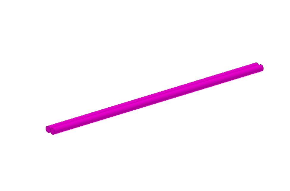
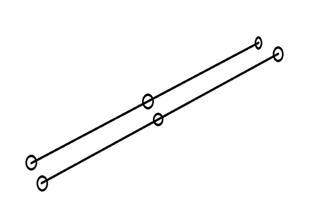
If, as an example, if we were looking at two circular beams next to each other,
idealised as two lines, meshed with a start middle and end node.
For this, what are the target segments?
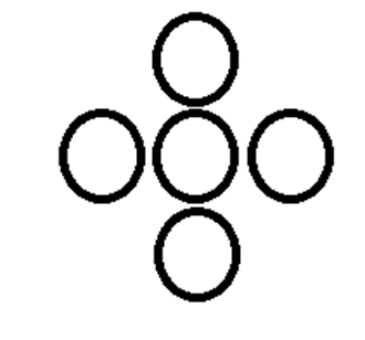
Are they along the length of the beam? Is it splitting the cross section up into x number of segments? Is it stating that essentially it is only tracking the number of adjacent beams to each node, so 1 would be fine here, but if there was beams above below and to left and right of a beam (in a cross arrangement such as shown on end view below) then 4 would be required?
or are the segments something different entirely? -
January 15, 2024 at 2:17 pm
Stella Peloni
Ansys EmployeeWhen we create a contact, some elements are created with them (target and contact elements). In the Documentation I attached, it says for example: “ In a pair-based contact definition, the 3D line contact elements (CONTA177) are associated with 3D target segment elements (TARGE170)”. So, in my understanding, the segments are the elements.
Regards,
Stella
-
January 16, 2024 at 8:53 am
Al Holmes
SubscriberThanks for the response Stella. Had a little think about this and still a bit confused.
Continuning the example above where I have two lines with the same sizing controls on them, one whole line scoped as contact and the other as target. For a given node on the target line I can imagine that it is proximity to 1 contact line and maybe 2 contact elements / segments. So if I select 8, what is it doing differently to if I select a 1 or 4?
Assuming that we then add three other lines around that original target line (forming that cross shape when looking at the end) and they are also all scoped as contact. The original target line now is target to 4 pairs of contact. How is that now being dealt with?
-
- The topic ‘line-lineDetection Terminology’ is closed to new replies.


- The legend values are not changing.
- LPBF Simulation of dissimilar materials in ANSYS mechanical (Thermal Transient)
- Convergence error in modal analysis
- APDL, memory, solid
- How to model a bimodular material in Mechanical
- Meaning of the error
- Simulate a fan on the end of shaft
- Nonlinear load cases combinations
- Real Life Example of a non-symmetric eigenvalue problem
- How can the results of Pressures and Motions for all elements be obtained?

-
3862
-
1414
-
1221
-
1118
-
1015

© 2025 Copyright ANSYS, Inc. All rights reserved.


