

-
-
September 18, 2020 at 10:20 am
andrefpitt
SubscriberHello all.
I'm facing a dilemma here while analysing the elements.
See photo 1, which is the element that I would like to analyse within the outer body. It's a fibre behaving as that shape.
September 18, 2020 at 11:21 ampeteroznewman
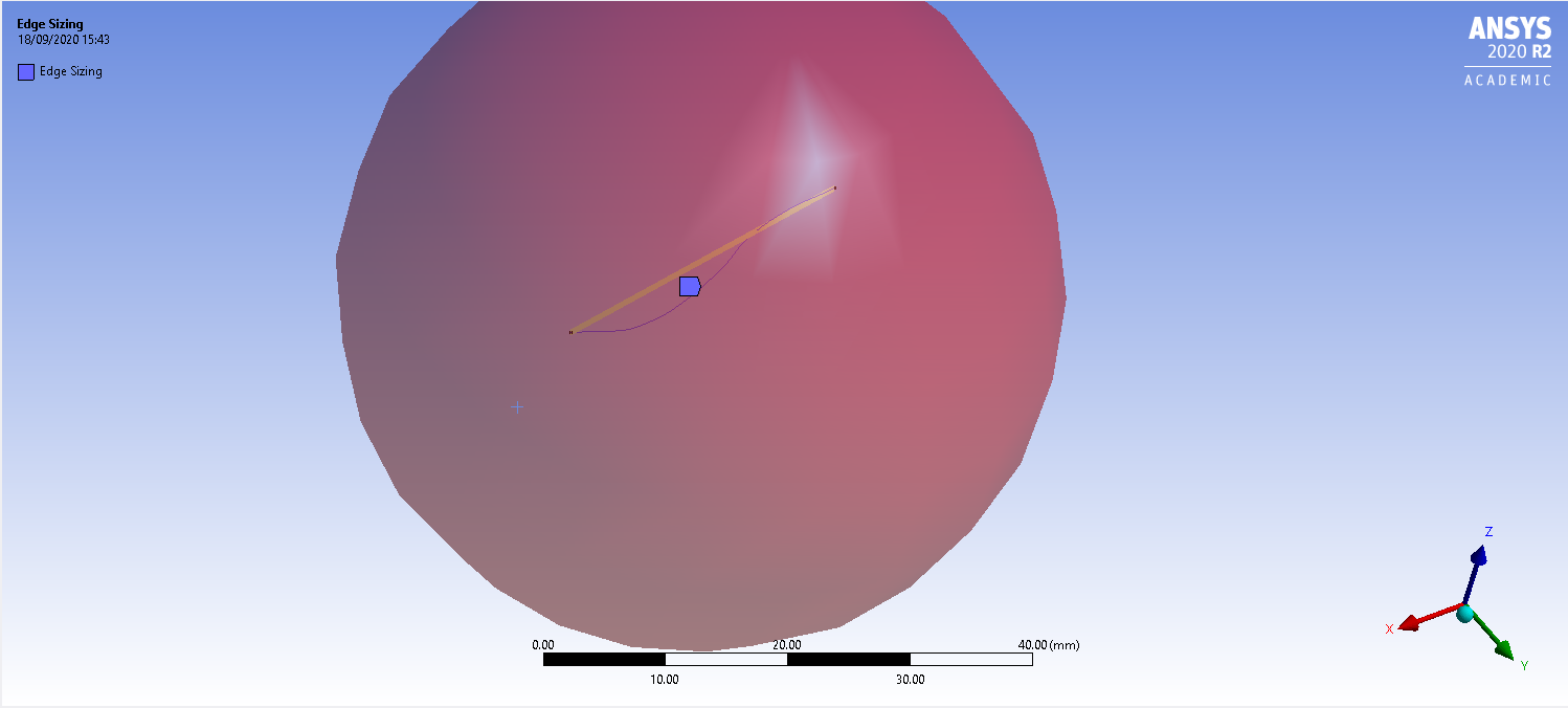
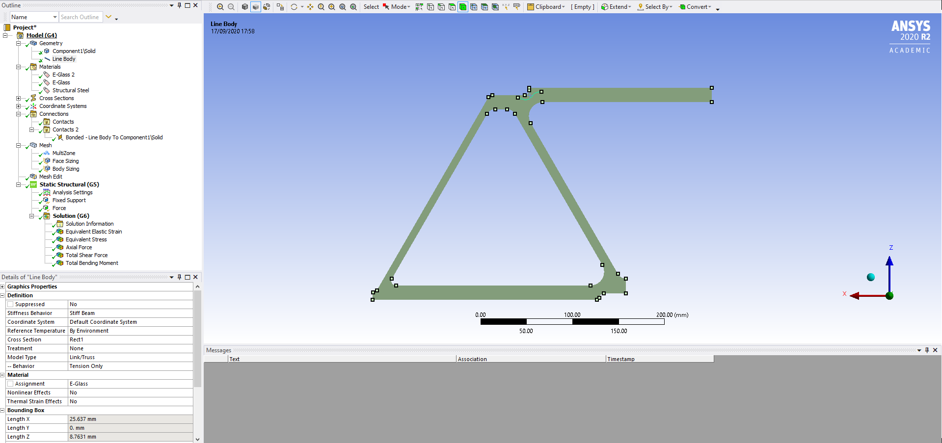
SubscriberYou need to add a Mesh control of Sizing on the line body and set the Element Size for that line body at 1 mm. It looks like there is only a single element. However, you want the nodes on that element to interface with nodes in the surrounding material. Therefore, I recommend you add a Coordinate System at the center of the line body, then add a Sizing mesh control on the frame of type Sphere of Influence, and set a Radius of 30 mm and an element size of 1 mm.nHave you already figured out how to connect the line body with the surrounding material?nSeptember 18, 2020 at 2:43 pmSubscriberDear Peter,nThank you for your time and your insightful comments.nThis is a photo using the body as a beam. (30mm and element size of 1mm)n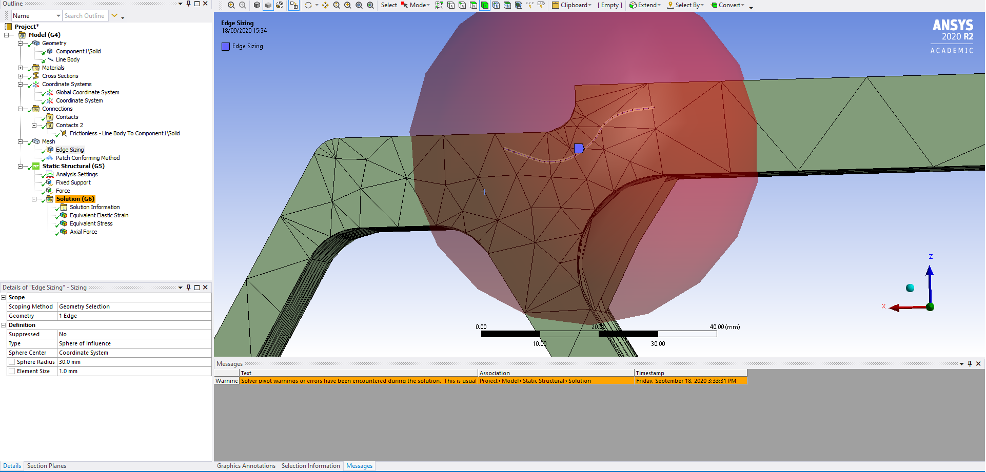 But how I would like to study as an axial member only (cable) it's still straigthen the cable upn
 I set a shared topology between the line body and the solid and added a frictionless contact between. But answering straight to your question about the connection between the bodies I would say no. I'm probably doing something wrongnI'm trying to study that line body and its behaviour, wouldn't be the best study as a crack?nAny suggestion is more than welcomenThank you very much, Peter, for your attentionn
 nn
September 18, 2020 at 4:57 pmSubscriberI know one way to connect the fiber to the solid, that is to create an edge in the solid that is coincident with the fiber.nIf the curves of the fiber are planar, then it is possible to slice the solid on that plane, then extrude the fiber into a cutting surface and slide the two solid pieces into four, then you will need a plane at each end of the fiber, normal to the fiber to cut the four solids at each end of the fiber to end up with 12 pieces.nAt that point, Shared Topology begins working because your line body and the solid bodies now share edges.nIf the fiber was not planar, but had a 3D curve, that just makes the job more difficult, but not impossible.nI can help with that slicing if you attach a zip file with your project archive. Make sure the Geometry is available for editing in that archive.nThere is another way to do this, using MESH200, and REINFORCE, but I have never used that. No slicing of geometry is required. The elements find the intersection with the beams all by themselves.nSeptember 18, 2020 at 7:46 pmSubscriberHi Peter,nThis is a tremendous help and generous of you.nFollow the folder with all workbench files and I also added a few SpaceClaim 2D and 3D drawings of the profile.nWorking that connection and being able to study the axial behaviour of the fibre will be great support so I can analyse the results to my dissertation.nPlease let me know anything that I can do to help you help me. nnThank you so much, PeternSeptember 18, 2020 at 8:55 pmSubscriberDear Andre,nAttached is the 2D Thick Fibre that I performed a Combine operation to subtract the fiber from the matrix, then used the Share button to connect the two surfaces.nI rotated this geometry into the XY plane so you could do 2D plane strain models. I made the matrix Aluminum and the Fiber Steel.n
nn
September 18, 2020 at 4:57 pmSubscriberI know one way to connect the fiber to the solid, that is to create an edge in the solid that is coincident with the fiber.nIf the curves of the fiber are planar, then it is possible to slice the solid on that plane, then extrude the fiber into a cutting surface and slide the two solid pieces into four, then you will need a plane at each end of the fiber, normal to the fiber to cut the four solids at each end of the fiber to end up with 12 pieces.nAt that point, Shared Topology begins working because your line body and the solid bodies now share edges.nIf the fiber was not planar, but had a 3D curve, that just makes the job more difficult, but not impossible.nI can help with that slicing if you attach a zip file with your project archive. Make sure the Geometry is available for editing in that archive.nThere is another way to do this, using MESH200, and REINFORCE, but I have never used that. No slicing of geometry is required. The elements find the intersection with the beams all by themselves.nSeptember 18, 2020 at 7:46 pmSubscriberHi Peter,nThis is a tremendous help and generous of you.nFollow the folder with all workbench files and I also added a few SpaceClaim 2D and 3D drawings of the profile.nWorking that connection and being able to study the axial behaviour of the fibre will be great support so I can analyse the results to my dissertation.nPlease let me know anything that I can do to help you help me. nnThank you so much, PeternSeptember 18, 2020 at 8:55 pmSubscriberDear Andre,nAttached is the 2D Thick Fibre that I performed a Combine operation to subtract the fiber from the matrix, then used the Share button to connect the two surfaces.nI rotated this geometry into the XY plane so you could do 2D plane strain models. I made the matrix Aluminum and the Fiber Steel.n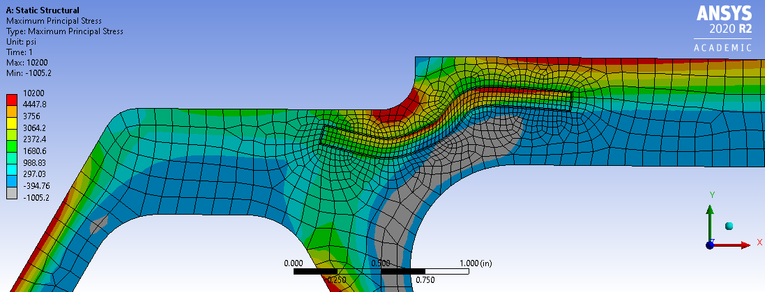 If instead of Shared Topology, you used Bonded Contact with Cohesive Zone Modeling you could allow the bond to break between the matrix and the fiber.nI don't know what you want to do with the single curve of beams because it is just sitting on the surface of the 3D solid. Did you want that to be a reinforcement of a different material, or simply an edge in a uniform matrix that would allow you to plot result quantities along that edge?nAlso, you left out the .wbpj file from the .rar file so I couldn't open your Workbench project.n
September 19, 2020 at 2:21 pmSubscriberDear Peter,nThank you, once again for all the support and my apologies for not sharing the right files with you.nThe command 'combine' that you explained, help me to create a thinner surface to study its behaviour. And the way that you meshed the elements taught me how to do it properly. Thank you!nI gave a shot to see if I can pull out the bonded contact but I was not able to extract the results from the connection. Perhaps I'm doing wrong? See photos below:n
If instead of Shared Topology, you used Bonded Contact with Cohesive Zone Modeling you could allow the bond to break between the matrix and the fiber.nI don't know what you want to do with the single curve of beams because it is just sitting on the surface of the 3D solid. Did you want that to be a reinforcement of a different material, or simply an edge in a uniform matrix that would allow you to plot result quantities along that edge?nAlso, you left out the .wbpj file from the .rar file so I couldn't open your Workbench project.n
September 19, 2020 at 2:21 pmSubscriberDear Peter,nThank you, once again for all the support and my apologies for not sharing the right files with you.nThe command 'combine' that you explained, help me to create a thinner surface to study its behaviour. And the way that you meshed the elements taught me how to do it properly. Thank you!nI gave a shot to see if I can pull out the bonded contact but I was not able to extract the results from the connection. Perhaps I'm doing wrong? See photos below:n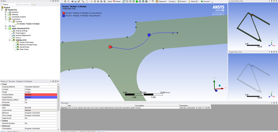 As I also said at the other post, is a way that I can study this surface as a fibre? Where it behaves like a hair, with only axial strength, no shear and bending resistance.nSee enclosed the file wbpj of the element abovenArraynNo words to thank you and Ansys Forum members for all the help.n
Viewing 6 reply threads
As I also said at the other post, is a way that I can study this surface as a fibre? Where it behaves like a hair, with only axial strength, no shear and bending resistance.nSee enclosed the file wbpj of the element abovenArraynNo words to thank you and Ansys Forum members for all the help.n
Viewing 6 reply threads- The topic ‘Line Body Working as a Truss – Cable. Only Axial forces’ is closed to new replies.
Ansys Innovation Space Trending discussions
 Top Contributors
-
peteroznewman
 3862
3862 -
scabo
 1414
1414 -
Dennis Chen
 1221
1221 -
javat33489
 1118
1118 -
Shyam Prasad V Atri
1015
Top Rated Tags
© 2025 Copyright ANSYS, Inc. All rights reserved.
Ansys does not support the usage of unauthorized Ansys software. Please visit www.ansys.com to obtain an official distribution.
-


The Ansys Learning Forum is a public forum. You are prohibited from providing (i) information that is confidential to You, your employer, or any third party, (ii) Personal Data or individually identifiable health information, (iii) any information that is U.S. Government Classified, Controlled Unclassified Information, International Traffic in Arms Regulators (ITAR) or Export Administration Regulators (EAR) controlled or otherwise have been determined by the United States Government or by a foreign government to require protection against unauthorized disclosure for reasons of national security, or (iv) topics or information restricted by the People's Republic of China data protection and privacy laws.


