-
-
July 29, 2024 at 1:10 pm
uzmayaqoob1960
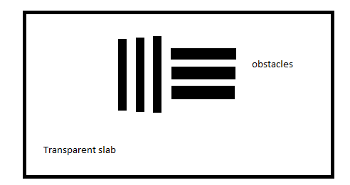
SubscriberI want to inquire can i illuminate a pattern attached below via a plane light source so that light gets block in some parts as per the provided pattern and when we perform metalensing then can we get pattern of these slabs on monitors ?.Suppose if i am using NIR (1550nm light then Aluminium slabs will block the incoming light plz guide if i am not wrong)
-
July 30, 2024 at 7:54 pm
Guilin Sun
Ansys EmployeeThis will depend on the working distances: you can definitely add such object in front to (attach to) the metalens, and use a monitor behind the metalens, and do the farfield projection to the focal plane, provided that you use plane wave source (with an iris/stop).
If there is an amplification, eg, the slab is located at some distance away from the metalens, it needs a lot of memory in order to directly image it. What you might do is:
simulate the slab with given illumination, and project the transmitted field on to the metalens front sourface (with small distance); then do the above simulation and post process the result.
-
August 1, 2024 at 9:50 am
uzmayaqoob1960
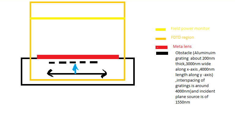
SubscriberDear sir i used to do the following setup for simulation .But when i simulate meta lens then focusing spot appears blockage of light in form of obstacles shadow couldn’t be achieved.Plz guide how could i do that?.Like in my substarte i am embedding Aluminium obstacles that could block light and transmit light according to the pattern.Sir u may suggest other materials too to properly block light.I will be really obliged.
-
August 1, 2024 at 8:17 pm
Guilin Sun
Ansys EmployeeYou may need to know how the image is produced: when the object distance is almost zero, the image cannot be real! what you got in the focal plane is the spatial spectrum of the obstacle in theory! Please check Goodman's Fourier Optics.
You have to find where the image is located in order to see the image. In your configurtion the object is located within one focal length the image will be not real at any distance after the metalens.
-
August 2, 2024 at 7:57 am
uzmayaqoob1960
SubscriberAlright sir many thanks then sir i have to place object on such a location so that its real image can be produced and we can capture it on monitor?
-
August 2, 2024 at 5:57 pm
Guilin Sun
Ansys EmployeeI am not sure what is the object distance. If it makes the simulation too large, you may do this in 3 steps:
1: using the source and the obstacle to do the first simulation, project the monitor data on to the front of the metalens, using farfield3D, including E and H:
https://optics.ansys.com/hc/en-us/articles/360034930733-farfieldexact3d-Script-command
2: using the projected EH data as import source, simulating the metalens. Using monitor data to define the spatial field profile of a source in FDTD
3: project the monitor data on to the inmage plane.
the two simulation files should be small, compared to simulate the whole process from object (the obstacle) to the image plane.
-
August 2, 2024 at 7:08 pm
uzmayaqoob1960
Subscriberok sir many thanks
-
- The topic ‘light source blockage in Lumerical’ is closed to new replies.


-
4989
-
1670
-
1386
-
1243
-
1021

© 2026 Copyright ANSYS, Inc. All rights reserved.


