-
-
November 15, 2024 at 1:53 am
hungnguyendinhbao
SubscriberHello
I am trying to simulate and calculate leakage inductance of transformer in Ansys
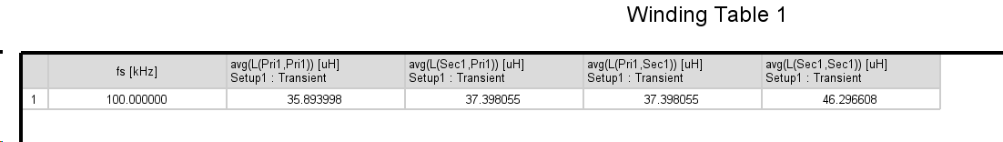
I attached 2 100kHz transformer core into 1 single core, the turn ration is 16:16 with 2 consecutive primary layer and 2 consecutive secondary layer, I put air gap to the winding leg to design magnetizing inductance, plz see the photo for more details.
But when I check and calculate Leakage inductance base on Self inductance and Mutual inductance result. The leakage inductance is big and only seen in secondary side. With symetrical winding like this I think the leakage inductance is same for both primary and secondary side.
Is there anyone having experience on this?. Please give me some instruction
-
December 5, 2024 at 9:41 am
Tamami Yamanaka
Ansys EmployeeHello,
If you see asymmetrical inductance, it could be due to several factors, including the physical geometry of the windings or the presence of the air gap you've introduced. It's important to first make sure that the actual physical layout in the windings, core, and air gaps matches the intended symmetrical design. Second, check that the mesh around the air gaps is fine enough. You can also simplify the design by removing the air gap and simulating with only one primary and one secondary winding, and then gradually add complexity back in to see where the asymmetry occurs.
-
- You must be logged in to reply to this topic.
- HFSS Incident Plane Wave excitement mode
- How to calculate eddy and hysteresis losses of the core?
- Ansys Maxwell 3D – eddy current
- Simulation of capacitor combining eddy currents with displacement currents
- dq graph non-conformity
- Simplorer+Maxwell Cosimulation results and Maxwell results mismatch
- Parametrizing coil “terminals” with coil geometry
- Maxwell circuit – PWM
- Plotting Ex, Ey and Ez in vector forms individually
- Calculating E-field tangential to a 2D resonant structure on a sapphire chip
-
1882
-
802
-
599
-
591
-
366
© 2025 Copyright ANSYS, Inc. All rights reserved.