
-
-
November 7, 2020 at 8:59 am
Rameez_ul_Haq
SubscriberHello there. We all know that 'large deflection on' effect makes the analysis non-linear, essentially by taking into account the geometric or in other words, element sizes' change and then modifying the stiffness matrix accordingly, on every iteration. The stiffness matrix here is a function of change in the displacements of the nodes itself for every iteration of each substep.nThe frictional and frictionless contact/support also causes the analysis to become non-linear, which means that the stiffness matrix is modified for every iteration of each substep. But my question is that why is frictional/frictionless non-linear? nFor a large displacement/strain, we know that we have to take into account the changes in geometry since the stiffness matrix itself is a function of geometry, but why does the frictional or frictionless contact makes the analysis non-linear? Is there a relation between the stiffness matrix and any aspect originating due to frictional/frictionless contact or support?n -
November 7, 2020 at 12:54 pm
peteroznewman
SubscriberArray
The stiffness matrix changes each time a node in the contact set comes into or out of contact with a target surface. Incrementing the load can cause a change in the contact, either nodes coming into contact or out of contact. That makes the problem nonlinear as the solver has to iterate to update the stiffness matrix after each contact change.
-
November 7, 2020 at 1:07 pmSubscriberThen why is the frictionless support non-linear, Array
-
November 7, 2020 at 3:21 pmSubscriberArray Frictionless support is a linear boundary condition. It works in linear analyses like modal and harmonic response. Nodes on the surface cannot separate in any analysis.
Frictionless contact is a nonlinear contact. Nodes on the surface can separate. ANSYS Mechanical will automatically convert a closed frictionless contact into a frictionless support in a modal analysis, but will ignore an open frictionless contact in a modal analysis. In a Static Structural or Full Transient Structural (not MSUP) the nodes in the contact can open and close as needed during the solution.
-
November 9, 2020 at 5:44 amSubscriberI understand what you mean Array. But if the nodes within the frictionless/frictional contact can actually open and close during the analysis, then what does the intiial cotact status (which can be open, far open, or closed) represent?
-
November 9, 2020 at 12:56 pmSubscriberArray
Closed means in contact, no gap.
Open (or Near Open) means not in contact, a gap, but being monitored by the solver during the solution
Far Open means not in contact and not being monitored by the solver. You can change a contact from Far Open to Open by increasing the Pinball Radius.
-
January 16, 2021 at 6:00 amSubscriberArray, can you please enlighten me with what does the pinball radius in a friction/frictionless contact mean? Does the stiffness matrix needs to get updated when the distance between the contact nodes and target face becomes greater than the pinball radius assigned? Or pinball radius can still be very high for friction/frictionless contact because that is just used to detect the contact between the two surfaces, and there is some other criteria to determine when the contact nodes are coming into or going out of contact from the target surface?
iI you can also tell me that why is the 'No separation' connection type a linear contact? Since the contact and target faces are allowed to slide onto each other, doesn't this mean that the stiffness matrix needs to be updated as soon as the sliding takes place because the new set of nodes on the contact face (which are now in contact with the target face) will now need to have a connection made to the target face?
-
January 16, 2021 at 1:17 pmSubscriberArray
The stiffness matrix gets updated when a contact pair sees a closed node open or an open node close. The criterion to decide if a node is open or closed is the gap/penetration of the node with the target surface.
The pinball radius is used to choose how many nodes to include in the set of nodes that will be monitored during the solution.
A linear analysis means the small displacement assumption is being used. At the start of the computation, each node is assigned to the face of a target element. That relationship will not change during the solution. Linear means no change in nodes that are open or closed.
-
January 17, 2021 at 6:12 pmSubscriberArray, sorry sir but I was not able to get the answer for the questions I asked. I am still confused about the 'No separation' contact. For Bonded, I know target and contact faces have no separation and no sliding, makes sense that it is linear. But for no separation, the two faces can slide over each other which might turn the initial contact from closed to open or vice versa. Still why is no separation considered as linear?
Assume I have two parallel surfaces of thickness 1 mm (and having a 2 mm of initial gap between the extended faces of the mid surfaces) where I want to apply a frictionless/frictional contact as soon as the gap between the extended faces of the mid surfaces becomes 0.5 mm [esentially meaning that the contact should become closed between these faces when the gap between them is equal to or less than 0.5 mm]. If I want to turn on the 'Surface effect', how can I model this contact? What pinball radius should be chosen? Will chosing a very high pinball radius like 10 mm, create a problem in correctly detecting the contact (closed and open) during the solution, instead of choosing a low but sufficient pinball radius like 0.75mm?
I think that if I choose 10 mm, then the initial contact status will be closed but it will remain closed even if the distance between the extended faces becomes greater than 0.5 mm, which I don't want to happen. I think that 0.75 mm makes sense because even if the initial contact status shows open, but when they come closer than 0.75 mm, the contact becomes closed. Does an initial contact status shown as 'open' for frictionless contact cause a problem during the solution?
-
January 18, 2021 at 3:24 amSubscriberBut for no separation, the two faces can slide over each other which might turn the initial contact from closed to open or vice versa. Still why is no separation considered as linear?
In a linear analysis, the small displacement assumption is being used so only small sliding is considered. If a node in a no separation contact is at the edge of a face, the node still behaves as if it is constrained to the plane of the face it started on, even if during the solution, the node moves off that element face and is now hanging out in space. It is up to you to check that the small sliding assumption is valid by carefully looking at the results.
Please make a sketch to illustrate your second paragraph, and even better, don't make it more confusing by talking about the shell thickness offset. All that work gets done behind the scenes. After that prep work, there is a Contact surface and a Target surface. There is either a gap or penetration between them at the start of a simulation. The frictional contact algorithm prevents penetration. If the gap is larger than the pinball radius at the start of the simulation, that contact pair is ignored during the simulation.
-
January 18, 2021 at 5:08 amSubscriber.
peteroznewman, sure sir. Beneath you can see an illustration.
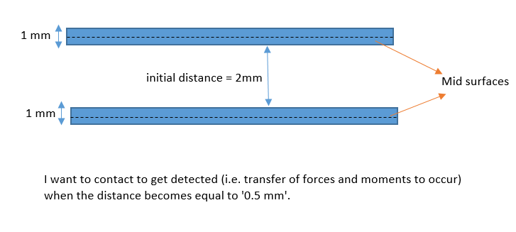 Now I hope you would be able to understand my previous question clearly :)
And I dont know sir why you said that it becomes more confusing by talking about shell thickness effect because if I turn it OFF, and if I input a pinball radius of for instance 0.75 mm, then the contact would only get detected when both the mid surfaces comes equal to or closer than 0.75 mm (but I want the contact to get detected when the extended faces of the mid surfaces becomes equal to or closer than 0.75 mm), am I not correct sir? I think this is a huge difference between shell thickness effect ON and OFF, which should always be considered.
. -
January 18, 2021 at 5:46 amSubscriberArray
In the example you show, with the shell thickness effect turned on, contact will transfer forces when the distance between between the midsurfaces is less than 1.0 mm since there is 0.5 mm of shell thickness effect on each body. Yet you say you want the transfer of forces to occur when the distance becomes equal to 0.5 mm. That is what I find confusing.
Now the initial distance you show is 2.0 mm, but that is to the contact and target surfaces, not the midsurface. In that example, the transfer of forces will occur when that measurement becomes equal to 0.0 mm.
I think you are confusing pinball radius with contact offset. Contact offset is the distance from the nodes to the contact surface. With shell thickness effect turned on, the contact offset is automatically set to half the shell thickness. If the shell thickness changes, the contact offset automatically updates to half the new thickness.
There are times when a surface is meshed with shell elements and Shell Thickness Effect is Off. In your illustration, imagine those blue solids had the faces of the solids that are closest to each other copied and pasted as surfaces. Now you would want the shell thickness effect turned off since the nodes are on the "outside face" of the solid. When this is done, it is possible to put the shell thickness on the correct side of the nodes. This is done by using a Section Offset. That means the center of the cross-section of the shell is offset from being on the nodes. In the example where the nodes are on the outside of the solid, the offset to the center of the cross-section is half the thickness.
As long as you use a large pinball radius, the contact offset will exactly determine when contact forces begin to be transferred.
-
January 19, 2021 at 11:15 amSubscriberArray, Now I am clear about the contact offset thing. If I am not wrong, Contact offset means translating the face of the contact (as well as the target) by half the surface thicknesses, when the shell thickness effect is turned ON, so that the transfer of forces happen on the these faces instead on the mid surfaces (where the nodes are located). If the shell thickness effect is turned OFF, then there is no Contact offset (meaning no translation of the faces where the transfer of forces will happen) and all the force transfer, for any type of contact, will occur directly on the mid-surfaces where the nodes are located. Correct me if I am wrong, please.
"If the gap is larger than the pinball radius at the start of the simulation, that contact pair is ignored during the simulation.", you wrote this in one of your previous comments. This means that even if the initial gap between the two surfaces is like for instance 2 mm initially for a frictionless/frictional contact, then I can safely choose 10 mm as the pinball radius to just make the contact to be monitored during the solution. Even making like 50 mm won't cause any difference right? I mean choosing 5 mm, or 10 mm or 50 mm are all the same.
But please try to understand this. I am still confused then how does the solver know like at this situation the frictionless/frictional contact is open and this situation it is closed, during the solution? I was thinking that the pinball radius might have an effect on the solver deciding on the situations which will cause the contact to become open or closed during the solution, but your comments alludes that it doesn't. I mean the solver can cause the transfer of forces and moments to happen from the start where an initial gap - maybe I am confusing the initial gap and geometric gap here, not sure - between the contact and target faces is 2 mm, or when the gap becomes 1 mm between them, or when these faces start to touch each other with gap of 0 mm. It means I have no control over the solver. Maybe I can write an APDL command to guide it to do what I want, but I don't this command to ask the solver to do what I want.
-
January 19, 2021 at 11:17 amSubscriberArray, can you also please tell me how can I achieve section offset for the surfaces? If for example I want the surface get extended in one direction only, instead of of equal and opposite directions. In other words, I donot want my surface to become a mid surface.
-
January 19, 2021 at 4:38 pmSubscriber.
Rameez_ul_Haq
All correct in paragraph 1.
A pinball radius of 5 mm, 10 mm or 50 mm are all the same when the two surfaces are parallel and the gap is < 5 mm.
Now if you have two parallel 100 mm diameter cylinders with contact defined and an initial gap of 2 mm, then there is a difference. The 5 mm pinball will only reach a little way up the side of the cylinder, while the 50 mm pinball radius will reach nearly up to the halfway point.
The solver uses the pinball radius to create new elements before the solution starts. The new elements are called CONTA and TARGE. The pinball radius controls how far up the cylinder the new elements are created.
In the illustration below, the line is 5 mm above the origin. If a pinball of 5 mm was used, there will only be contact elements on the yellow part of the cylinder, even though the entire cylindrical surface is scoped to be in the contact definition.
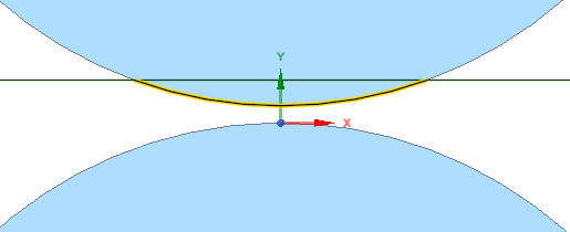 If you use a pinball of 5 mm and the loads cause the top cylinder to move sideways and downward to about 25 mm down the side of the other cylinder, the solver will run out of contact elements and it will fail to converge. In that case, the pinball radius should be 50 mm to capture about half the cylindrical surface. But if the loads and constraints keep the top cylinder center on the y axis, then a 5 mm pinball will work perfectly fine.
Back to Shell Elements, the way you tell the solver which side of the nodes you want the thickness of the cross-section is done in the Details Window of the Surface.
. -
January 19, 2021 at 8:33 pmSubscriberArray, thank you for such a helpful answer.
"The pinball radius controls how far up the cylinder the new elements are created.", which cylinder? Both cylinders? Or only the one with contact face? Or only the one with target face?
"In the illustration below, the line is 5 mm above the origin. If a pinball of 5 mm was used, there will only be contact elements on the yellow part of the cylinder, even though the entire cylindrical surface is scoped to be in the contact definition.", You used origin to address the center of sphere of pinball, but where actually is the pinball radius measured from though? Because whenever we use the pinball radius option in any type of contact, it just randomly pops up on a point on the contact face. This is an important question I think because it will determine the total number of CONTA or TARGE elements to be created.
-
January 19, 2021 at 11:50 pmSubscriber.
Rameez_ul_Haq
A frictional contact has a Contact face and a Target face. The pinball is used on every node of the Contact face. On a particular node, if the pinball reaches the Target face, a contact element is created. On another node, if the pinball does not reach the Target face, no contact element is created.
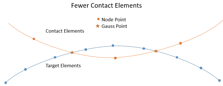
In the illustration below, you can see the first node on the left has a 5 mm pinball radius that does not reach the target surface below, so no contact element is created on node 1. Nodes 2 - 8 have a pinball that does touch the target surface so they get contact elements. Nodes 9 and 10 have a pinball that does not reach the target surface so they don't get contact elements.
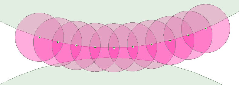 While the pinball is displayed at a random location, it is only the pinball size that is relevant, and you have to look at that and the geometric gap and decide if the pinball is too small, as you survey the area of the contact and target faces and decide how far away you require contact elements to be created.
Contact elements are computationally expensive, while Target elements are cheap, so I believe Mechanical covers the entire target surface with Target elements, while the pinball radius determines how many of the contact surface nodes get Contact elements.
. -
January 20, 2021 at 9:12 amSubscriberArray, so clear and understandable explanation. Thank you Sir!
-
February 10, 2021 at 11:33 amSubscriberArray, why is this general rule of thumb that the coarse mesh should be target face while finer mesh should be contact face? If contact elements are computationally expensive, then shouldn't the coarse mesh be given the contact face? Since less number of elements would then be given the CONTA element type.
-
February 21, 2021 at 9:14 pmSubscriberArray, an answer from you on this one would be very much helpful.
-
February 22, 2021 at 4:17 amSubscriber.
Rameez_ul_Haq By default, contact is detected at Gauss Points. The illustration below shows contact elements half the size of target elements. This shows zero penetration.
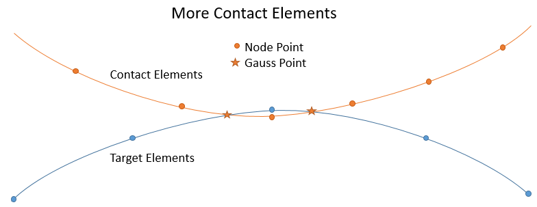 The illustration below shows target elements half the size of contact elements. This shows zero penetration. Note that the real penetration is larger than the reverse element size shown above.
. The extra elements on the target side don't really do anything to better define the shape of the target surface. I hope this explains why it's better to have contact elements to be smaller than target elements.
 -
February 22, 2021 at 1:21 pmSubscriberArray, what I understood is that the penetration increases in the case of target having smaller elements than the contact. But I couldn't grasp the reason behind it, I mean why does the penetration increase in this case, as compare to the case where contact has smaller elements than the target, and how can that be a problem, or maybe not any problem?
Plus, if the shell thickness effect is turned OFF, then we shouldn't be careful in defining the contact shell face and target shell face, right? I mean that the Shell thickness effect OFF makes the contact insensitive of the Top/Bottom option for each of these shell faces, right?
-
February 22, 2021 at 6:45 pmSubscriberArray
Physical penetration increases when the contact elements get larger. The reason is the Gauss Points get further apart. The curvature in the Target surface then poke further into the other body in physical terms, even though the mathematical evaluation of contact penetration is zero.
Shell thickness effect is independent of what I am showing. I am showing the contact elements. I don't care if those contacts elements are sitting on top of the shell elements (shell thickness OFF) or if the contact elements have been offset from the shell elements (shell thickness ON).
-
February 22, 2021 at 7:42 pmSubscriberArray, but what is going to be a problem in my analysis or results, because of what you said in paragraph 1?
Yeah sir ofcourse shell thickness effect is independent of what you were explaining. That shell thickness effect question is kind of like a side question. I would be glad if you could answer that as well.
-
February 22, 2021 at 10:59 pmSubscriberArray
Only you can decide whether the physical penetration is a problem in your analysis. I have seen interference fit problems that needed smaller tolerance values on allowable penetration in order to get accurate results.
I don't understand what you are asking about with the shell thickness effect.
-
February 23, 2021 at 5:16 amSubscriberArray, when I try to use a contact between two surface bodies, I get an option to choose Top or Bottom for each, i.e. Contact shell face and target shell face, right? I am simply asking if I turn OFF the shell thickness effect, then choosing the Top or Bottom for the contact shell face and target shell face will become completely irrelevant right? Since the force transfer would be occurring on the mid surfaces only.
If I have the shell thickness effect turned ON, then only choosing the correct Top or Bottom face for contact shell face and target shell face will be meaningful, right?
-
February 23, 2021 at 1:26 pmSubscriberArray
Imagine you have two horizontal shell bodies that are touching with frictional contact with shell thickness turned OFF. One body moves upward. Does that create a gap or penetration? It depends on how you set the Top and Bottom entries on the contact definition. Only you know if you intend that movement to be a gap or penetration.
-
February 24, 2021 at 12:32 pmSubscriberArray, If I have two horizontal surface bodies (one on top of other), and in reality they have a contact. However, during the modelling and after giving the thickness to them, the thickened faces of surface bodies penetrate each other. Imagine I don't have resources to move the bodies a little apart from each other so that their thickened faces just touch. Instead, I opt to go for Shell Thickness Effect OFF, so that the mid surfaces (which actually have a certain distance between them) can have the contact instead. In this case, choosing the Top and Bottom for contact and target shell face matters or not? I don't think it matters since the force transfer would now directly be happening on the mid surfaces instead of the thickened faces of each surface. CORRECT ME IF I AM WRONG.
Would it make a difference if the contact is LINEAR or NON-LINEAR?
-
February 25, 2021 at 12:06 amSubscriberArray
You describe the same scenario I gave you to imagine. For Frictional contact between shell faces, correctly choosing Top and Bottom matters. It is the difference between a normal movement of one surface relative to the other creating a gap or a penetration. You are wrong if you think it doesn't matter. For Bonded Contact, Top and Bottom doesn't matter because the two surfaces have no relative motion. We are only talking about Nonlinear Contact.
Linear contacts don't have gaps or penetration so they are like Bonded Contact.
-
February 25, 2021 at 8:59 amSubscriberArray, but even for the Non-linear contacts like frictional/frictionless, the Shell thickness effect OFF is making the force transfer to happen on the mid surfaces. In the reality, the situation is different I agree since there doesn't exist any shell elements, only 3D elements exists. But I couldn't understand WHY DOES IT MATTER IN ANSYS IF I CHOOSE WRONG TOP/BOTTOM FACES OF THE SURFACES IN CONTACT, since the non-linear contact is between the mid surfaces, all the force transfer will be on the mid surface and then distributed/interpolated to the thickened faces of each surface. Maybe you are thinking in terms of reality, but I am thinking in terms of ANSYS only, like should I expect a difference in stresses on the surfaces if I turn OFF shell thickness effect, and firstly correctly choose the Top/Bottom faces, and then wrongly choose Top/Bottom faces.
-
February 25, 2021 at 12:55 pmSubscriber.
Rameez_ul_Haq
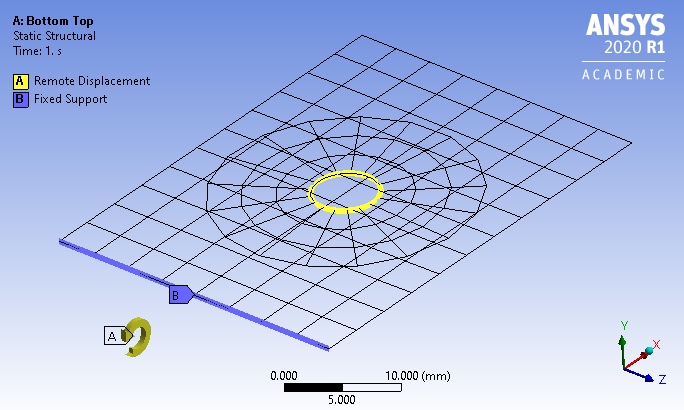
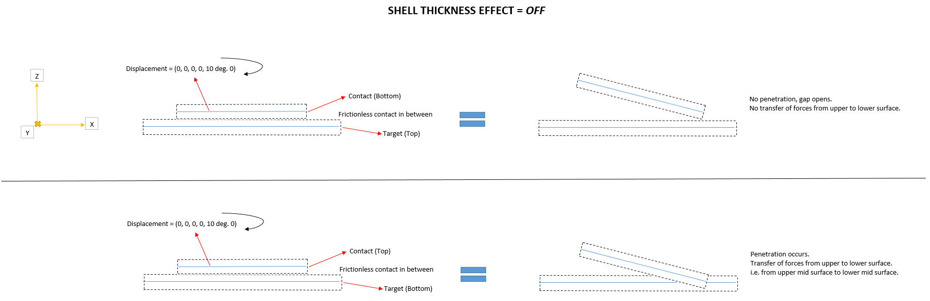
Below is the example I have been describing. Two shell meshes are in the same plane. The long part is fixed on the left edge. The short circular part has a remote displacement that applies a 5 degree rotation about Z. Frictional contact is defined between the two surfaces. The Target side is the long rectangle. The Contact side is the short circle.
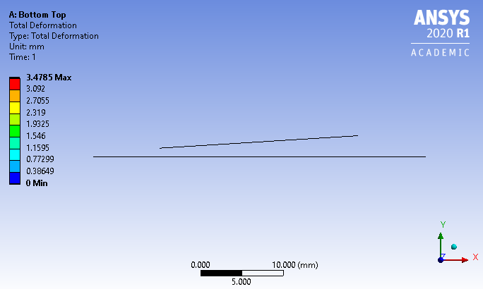
Below is the result when the Contact on the short part is set to Bottom and the Target on the long part is set to Top. A gap opens up.
Below is the result when the Contact on the short part is set to Top and the Target on the long part is set to Bottom. Penetration causes deformation of the long part.
.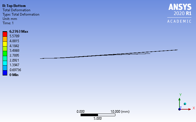 I hope you now understand why Top/Bottom matters.
 -
February 25, 2021 at 5:21 pmSubscriberArray, was the shell thickness effect turned OFF or ON in this example?
-
February 26, 2021 at 2:33 amSubscriberArray
Shell thickness effect was turned OFF.
-
March 4, 2021 at 1:35 pmSubscriber.
peteroznewman, please observe my explanation below. Please correct me if I am wrong.
.
-
March 4, 2021 at 7:26 pmSubscriberArray
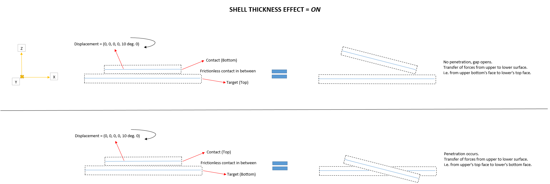
Shell Thickness Effect is separate from Contact Top/Bottom selection. Shell Thickness Effect simply automates adding an Offset (No Ramping) to the Contact definition. If the surfaces are modelled as midsurfaces, then turn Shell Thickness Effect ON. If the surfaces are the outside face of the underlying solid, then turn Shell Thickness Effect OFF.
Contact Top/Bottom depends on the surface normal. You can have a contact working the way you want it to, then go to the geometry editor and flip the surface normal, and when you update the geometry into Mechanical, the contact will not be working the way you want it to until you flip that side of the contact to the opposite of what it was (Top or Bottom).
-
March 5, 2021 at 6:49 amSubscriberArray, so what you said in the last paragraph means that I always have to check first if my contact is working the way I want it to after conducting the analysis, and if it is not, then I am supposed to change the Top/Bottom for contact and targets, until it starts working the way I want it to. So basically, this leaves me with 4 combinations and I have check each and every one and conduct an analysis for each to confirm which one is behaving in the correct manner.
-
March 5, 2021 at 12:57 pmSubscriberArray
There are 4 combinations and only one is correct for a particular contact pair. You don't have to check each one by solving an analysis. There is graphical feedback on the surface when the contact is selected on which side of the surface is air (the other side being material). If you are looking at the air side, you see a solid color, if you are looking at the material side you see a transparent surface. The solid color is red or blue depending on whether it is the Contact or Target.
That means you can create a contact and by rotating the view to look through the surfaces from two directions, immediately change each side to the correct setting of Top or Bottom if one or both are wrong. This should be done for surfaces brought in to Mechanical.
When you bring solids into Mechanical and pick two faces to be Target and Contact sides, the contact Top/Bottom assignment is always correct because of the convention that face normals always point outward, so when you look at them from the air side, they will appear solid.
-
February 20, 2022 at 2:33 pmSubscriber.
peteroznewman, just had a question and I would glad if you could answer.
Assume I constructed a frictional contact between faces of two solid bodies. Now, one face is smaller than the other and this face was given the 'contact face' status. Now this contact face can come into contact with all of the target elements, right? What I mean is that there is no limit for this contact face to come into contact with just a few nearby target elements, right? The huge face of the other solid body that was chosen as target has target elements all over its face, and it is possible for the contact face of the other solid body to come into contact with any of these target elements, right?
. -
February 20, 2022 at 3:59 pmSubscriber.
Rameez_ul_Haq
There is a setting on the Contact Details called Trim Contact. If that is set to ON, after the initial evaluation, it will remove individual contact elements that are Far Open, so it will not be possible for the small surface to slide anywhere on the large surface. If Trim Contact is OFF, then no contact elements are removed and it will be possible for the small face to slide anywhere on the large face.
If you leave Trim Contact to Program Controlled, then it depends on what version of ANSYS you are using because I think they changed the default at some point in the past. If you are concerned, don't leave it Program Controlled, set it yourself.
. -
February 20, 2022 at 4:27 pmSubscriber.
peteroznewman, thanks. So basically (if I got it right) if I set the Trim contact to ON, then only those Target elements can come into contact with the Contact elements, to which atleast one contact node can reach with the defined pinball radius. If any target elements doesn't have atleast one node of the contact face reaching to it with the defined pinball radius, then it is not possible to track the frictional contact between these target elements and the contact elements. Correct?
. -
February 20, 2022 at 4:30 pmSubscriber.
Rameez_ul_Haq I don't know the exact details of how they wrote the Trim Contact algorithm, but it is something like what I described.
. -
August 31, 2023 at 7:03 pm
Kenneth Ekpo
SubscriberDoes turning on Large Deflections with majorly frictional or frictionless contacts make convergence more difficult?
-
- The topic ‘‘Large deflection on’ non-linearity VS ‘frictional/frictionless support or contact’ non-linearity.’ is closed to new replies.


- LPBF Simulation of dissimilar materials in ANSYS mechanical (Thermal Transient)
- Convergence error in modal analysis
- APDL, memory, solid
- Meaning of the error
- How to model a bimodular material in Mechanical
- Simulate a fan on the end of shaft
- Real Life Example of a non-symmetric eigenvalue problem
- Nonlinear load cases combinations
- How can the results of Pressures and Motions for all elements be obtained?
- Contact stiffness too big

-
peteroznewman
 4167
4167 -
scabo
 1487
1487 -
Dennis Chen
 1363
1363 -
javat33489
 1194
1194 -
Shyam Prasad V Atri
1021


© 2025 Copyright ANSYS, Inc. All rights reserved.


