TAGGED: large-deflection, non-convergence, structures
-
-
March 3, 2024 at 10:35 pm
Marcin Nowak
SubscriberHi everyone,
I am solving a quite simple problem of pipe undergoing pressurizing up to about 10 kPa. Static structural. The model is solved succesfully even with 1 substep when large deflection=off:
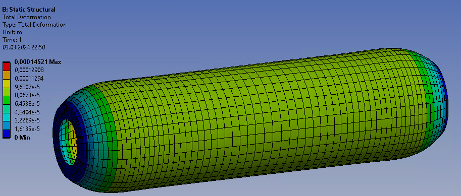
However, setting large deflection=on, cause non-convergence, with a standard warning "The solver engine was unable to converge on a solution for the nonlinear problem as constrained". I tried auto time stepping with many substeps on the level of 1000 without success.
Below I listet what I tried:
- changing mesh number of elements through thickness, as 1, 2, 3 or 4 - no effect on convergence,
- changing mesh density through the pipe length, as the higher gradients are in the endings regions - no effect,
- changing the pressure boundary condition, as if it linearly increases from the endings to the final value (depicted below) - didnt help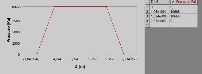
- trying to use tetrahedral mesh instead, with Nonlinear Adaptive Region option activated - without success,
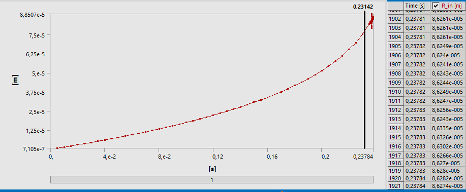
- activating Semi-implicit option - I just putted command "SEMIIMPLICIT" i.e. without editing this utility' options. This allowed me to solve greater part of the load, however with the extreme deformations which were growing rapidly within the last solved steps, as depicted below on the true-scale deformation field and the charts: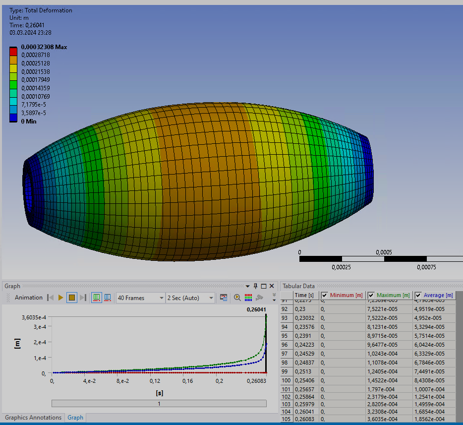
- tuning settings of the Analysis settings ->nonlinear controls -> stabilization; to my suprise this got completely no effect, no matter what option of stabilization I choose or what values of constants I put, I can even completely turn off stabilization and have the same substeps number solved, as for stabilization=program controlled (or some option manually chosen)
I am aware, that in such problems the issue might be simply, the relation between the Young modulus and loads. In my model, I got very small pipe (diameters about 0.3 milimeters), Young modulus about 21 kPa and inside pressure 10 kPa. I can succesfully solve the large-deflection model for decreased pressure to max 2.5 kPa, or with pressure unchanged (10 kPa) but increased Young modulus, up to 100 kPa, if I remember correctly.
Hovever, in my opinion I got correct model, geometry and material properties, which I concluded based on three things: 1) large deflection=off model results, 2) analytical model results, 3) experimental results. All three results are similar. Therefore I still think, that this is the issue of stabilizing the solver, which I am trying to do.Please guide me, what I might also try to solve the issue,
Kind regards -
March 4, 2024 at 4:43 pm
dlooman
Ansys EmployeeIt looks like your cylinder will explode with the pressure you are specifying. Your solution with large deflection off appears to have doubled the diameter of the cylinder. That will double the hoop stress as well, so now the displacement will double. This doubling will continue to failure.
-
March 4, 2024 at 10:39 pm
Marcin Nowak
SubscriberThank you for the answer, I understand, however, what conclusion would be here? The Young modulus for the large deflection model should be higher than for small deflection?
-
-
March 5, 2024 at 3:58 pm
dlooman
Ansys EmployeeLarge deflection is the "real life" solution. If it says you need a higher modulus you need a higher modulus. You can't go by the small deflection result.
-
March 6, 2024 at 7:48 am
hdonner
SubscriberHi Marcin,
in case of pressure loads in combination with large deflection, the stiffness matrix becomes unsymmetric. Thus, please go to Analysis Settings -> Nonlinear Controls -> Newton Raphson Option = Unsymmetric.
Further, if this stability issue appears, which is mentioned by Dave, I would activate quasi-static solution in the Analysis settings. Please take care that the material has a density. Last but not least, I would set the max. number of substeps to 1e9, allowing Ansys using very small time steps.
Were these hints successful?
Kind regards
Hendrik
-
March 6, 2024 at 8:17 pm
Marcin Nowak
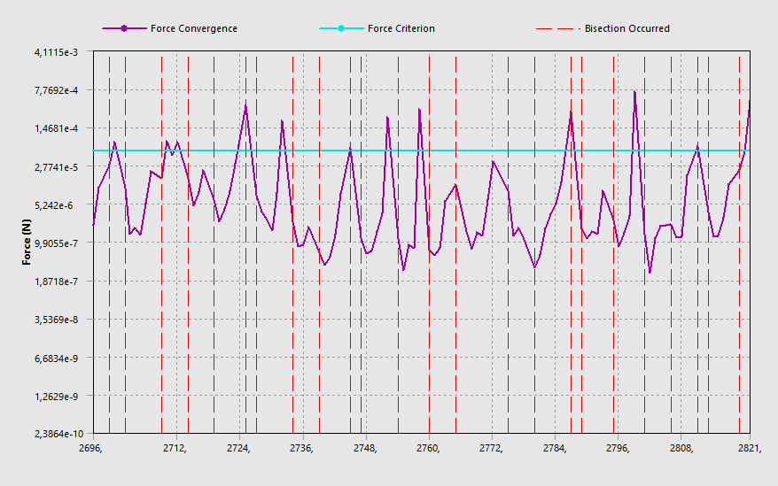
SubscriberI putted all the settings that you proposed, firstly separately, then all them together, and I dont get convergence. Still standard error "The solver engine was unable to converge ...". I get effect presented on the screens below. The force convergence is not obtained, displacement on the other hand is. I created the Result trackers, for the node in the inside and outside of the cyllinder. The location 'inside' is diverging (ups and downs) during the last steps. The location 'outside' is stable. The timestep at the end of solving is very low.
-
-
March 6, 2024 at 9:44 pm
dlooman
Ansys EmployeeYour vessel radius appears to be around 10e-5 meters. If R_in is the radial displacement in meters, you are approaching a solution in which the radius has almost doubled. The model is probably unstable at that point.
-
March 6, 2024 at 10:47 pm
Marcin Nowak
SubscriberYes, the diameter doubles, also in the experiment.
What do you mean by "the model is unstable"? I know that the solver is unstable, which I am trying to stabilize without success;
What can I do to made my model stable?
-
-
March 7, 2024 at 7:27 am
hdonner
SubscriberHave those modifications enabled the simulation of a higher load level?
From a mathematical point, unstable means that the stiffness matrix becomes singular and, in a purely static analysis, your displacement increments tend to infinity even for infinitesimal load changes. But usually, intertia effects, activated by quasistatic solution, will help overcoming this point since it regularizes the problem. Of course, if you have local instabilities this might not help. I also sounds like an instability to me. The question is now: is it realistic or artificial due to modelling defeciencies.
It is hard to judge this without reviewing the model.
Can you answer the following questions:
- Can you tell us which material this is in reality? 21 kPa Young’s modulus is extremely soft (sounds like a biological tissue? ).
- Which strains appear in your model near the critical point? According to the change in radius, it sounds like ~100 % engineering strain?
- Which material model do you use (isotropic elasticity?) and is it maybe to simplified compared to the real material (hyperelasticity and maybe reinforced like artery wall)?
- Does this test has also been carried out in reality so that you know that it works at this pressure level?
Kind regards
Hendrik
-
March 11, 2024 at 5:43 pm
Marcin Nowak
SubscriberNo, they have not.
- This is a biological tissue,
- the radius increases by about 80 micrometers as indicated in the attached pictures in previous post (diameter almost doubled) then simulation crashes. This happens for about 24% of the load (the load is internal pressure of 10 kPa). For the small deflection model, the final diameter (for final load) is approx. two times the initial.
- Yes this is artery, with applied linear elasticity and I would like to solve it for such material model,
- Yes the real experiment was done, for such pressure the similar deformations are observed (approx. doubled diameter)I am wondering whether changing the simulation type from the Static Structural to Transient Structural may help? As this is a practice used in the fluid mechanics. However in my static structural analysis I set multiple substeps so probably it would not make a difference
-
March 12, 2024 at 8:37 am
hdonner
SubscriberYour idea of activating Transient Structural is good. But if you activate quasi-static solution in static structural, this is the same since quasi-static means transient structural with high numerical damping. Check the doc especially 5.6.3:
5.6. Transient Dynamic Analysis Options (ansys.com)
Ok, so as I expected regarding the material. Note, the isotropic elastic material model is only stable for small strains. In case of modelling biological tissues, hyperelastic material models are state of the art and required. I would recommend to start with Neo Hooke hyperelasticity. This is still a rough approximation because artery walls are highly ansiotropic and this is usually modelled with anisotropic hyperelasticity:
8.5. Modeling Material Nonlinearities (ansys.com)
I would recommend doing a literature survey on models for artery walls and especially parameter sets.
But an initially much better approximation compared with isotropic elasticity will be hyperelasticity. You can convert the parameters as follows
- Take the shear modulus from your existing isotropic elastic model (you can find it in the Engineering data) and use it directly as initial shear modulus.
- Take the bulk modulus and convert it to the incompressibility parameter D1 or d = 2 / K. So if K equals 2000 MPa, than D1 or d = 0.001 MPa^-1.
If you do so, the small strain behavior of both models will be equal. Note, if the material behaves nearly incompressible (nu > 0.49) you need to activate u-p formulation. For Solid185 this is possible via an APDL snippet.
keyopt,matid,6,1
My settings would be (apply all simultaneously):
- Neo Hooke instead of isotropic elasticity
- u-p formulation in case of incompressibility
- Quasi-static solution (assign a density!)
- Unsymmetric stiffness matrix
- Maximum substeps 1e9
-
-
- The topic ‘Large deflection convergence problem’ is closed to new replies.


-
5024
-
1709
-
1387
-
1248
-
1021

© 2026 Copyright ANSYS, Inc. All rights reserved.

