Hi Peter,
Thank you very much for your detailed explanation and suggestions, I really appreciate your help. I think your approach using a thermal-only model is very interesting and I will likely use it later for my study (I believe this is the study I will finally use as a result because Coupled module is too demanding..).
Before moving to that approach, I would like to further explore the coupled-field simulation, since although it is more computationally expensive, it is also more physically representative of the braking process. Even if I only capture the temperature increase in the pad and disc (without fully modeling heat transfer to the rest of the assembly), it could still be a valid and useful result.
I have already simplified my model in a similar way to yours (keeping only the disc and pads, removing other components, and ensuring initial contact), but I have not yet applied symmetry like you did. However, the simulation is still extremely slow and progresses very little over time.
Since you mentioned that your simplified model solved in about 1 hour and produced a temperature increase, I was wondering if you could please share a bit more detail about your setup. In particular:
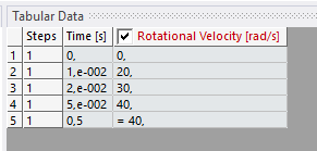
- The values and time evolution you used for rotational velocity
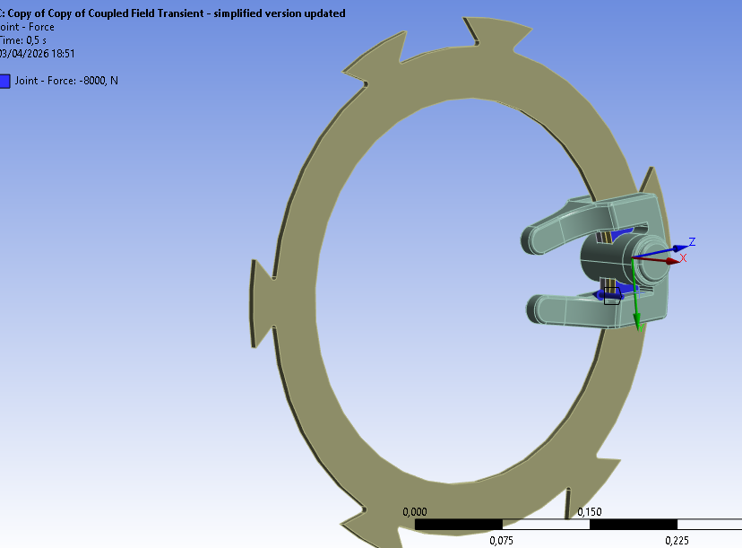
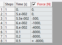
- The force applied on the pad (and how it is defined)
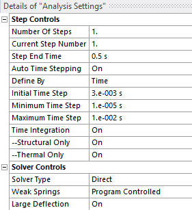
- Your Analysis Settings (time stepping, etc.)
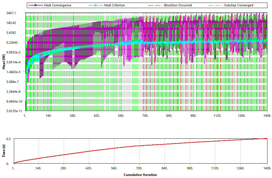
I feel I may be missing something important, as my setup seems conceptually similar but is still much slower.
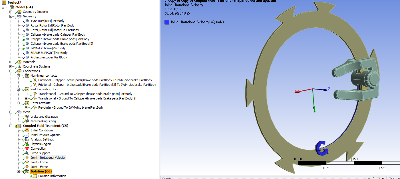
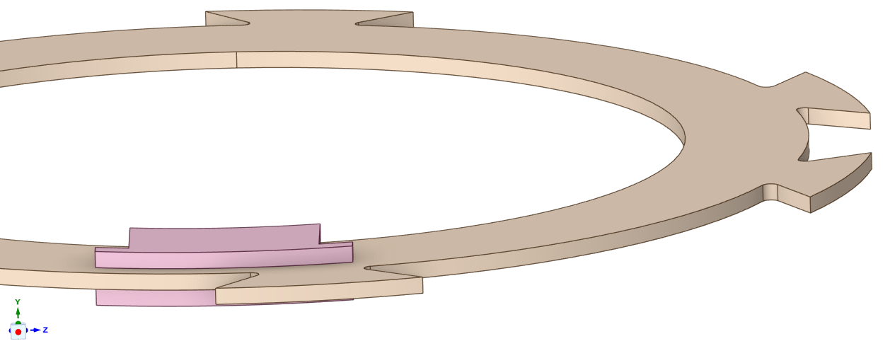
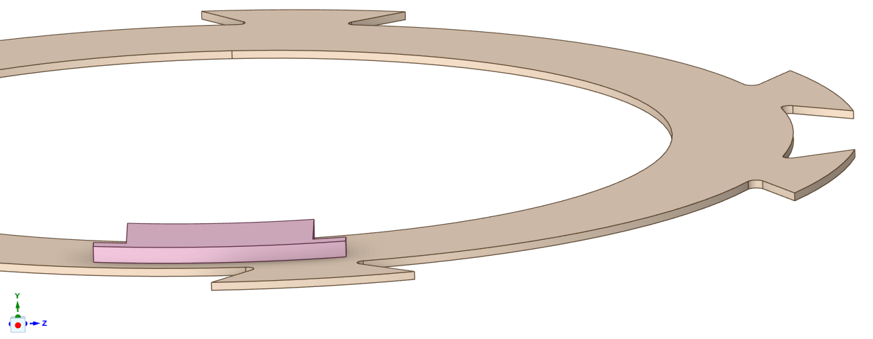
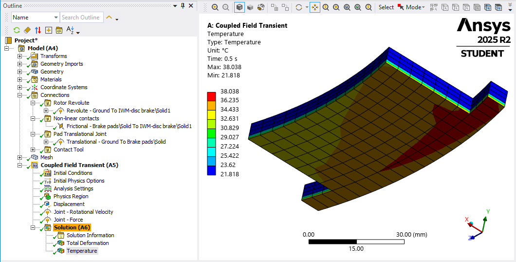
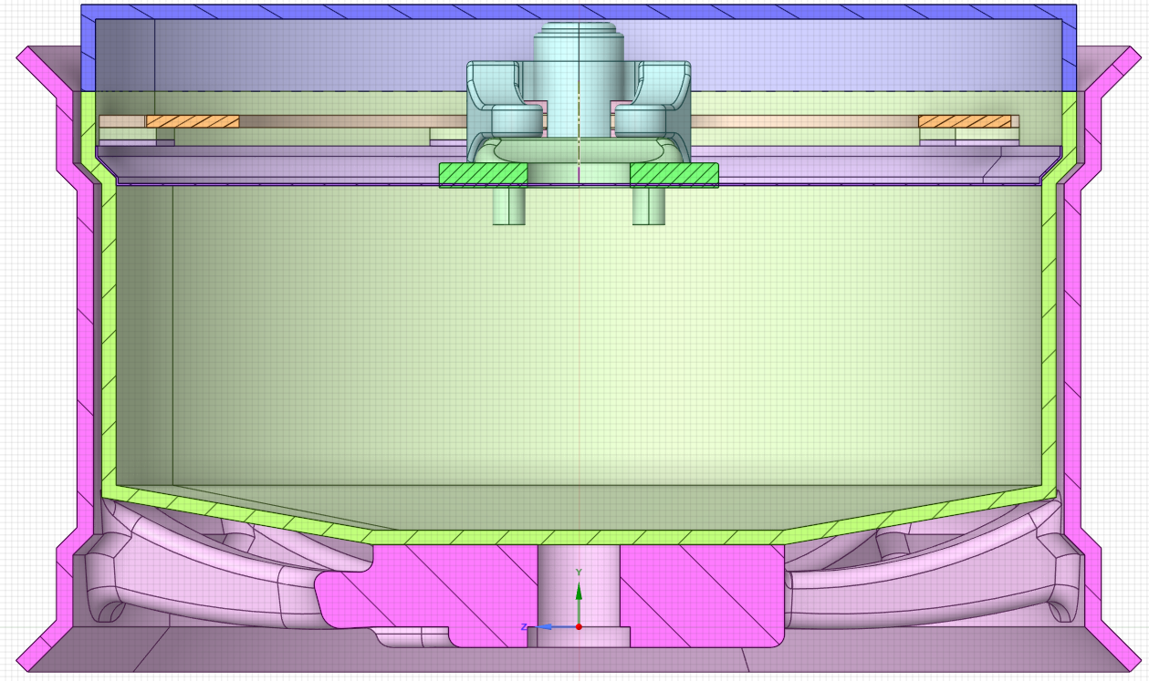
I’ve attached a few screenshots of my current setup for reference.
Thanks again for your help, it’s been very valuable.
Hi Peter,
Thank you very much for your detailed explanation and suggestions, I really appreciate your help. I think your approach using a thermal-only model is very interesting and I will likely use it later for my study.
Before moving to that approach, I would like to further explore the coupled-field simulation. Although it is more computationally expensive, it is also more physically representative of the braking process. Ideally, I would like to observe how temperature evolves not only at the contact but also across the different components. However, I understand that the main heat generation occurs at the pad–disc interface, so even if I only capture the temperature evolution of the pads and disc, it would still be a valid and useful result.
The idea is later to compare this with a conventional open braking system, where I would apply convection to represent airflow and expect lower temperatures. So even a simplified coupled result focusing on pad and disc temperatures would still be meaningful for comparison. I would like to explore this option fully before moving to the thermal-only approach.
I have already simplified my model in a similar way to yours (keeping only the disc and pads, removing other components, and ensuring initial contact), although I have not yet applied symmetry. However, the simulation is still extremely slow and progresses and now, it has failed to converge. So the last option is trying to know what setup values you have applied and use the same in orther to obtein the results you shared (then I coul increase the time to obtein a higher temperature).
Since you mentioned that your simplified model solved in about 1 hour and produced a temperature increase, I was wondering if you could please share a bit more detail about your setup. In particular:
- The values and time evolution you used for rotational velocity
- The force applied on the pad (and how it is defined)
- Your Analysis Settings (time stepping, etc.)
I feel I may be missing something important, as my setup seems conceptually similar but behaves quite differently. Even obtaining reliable temperature results just for the disc and pads would already be very helpful at this stage.
I’ve attached a few screenshots of my current setup for reference.
Thanks again for your help, it’s been very valuable. If it still does not converge with your setup ifnromation or progress properly, I will move on to the thermal-only approach you suggested.