3D Design

3D Design

Topics related to Ansys Discovery and Ansys SpaceClaim.

Issues with Solidworks model in ANSYS

    • RDelaCourt
      Subscriber

      Hello,


      I want to analyse a chassis crashing into a rigid wall at speed (50m/s) by utilising the Explicit Dynamics solver.


      I have created a tubular spaceframe chassis on Solidworks using the weldment feature but I am having trouble with the geometry when i import it into ansys spaceclaim.


      I have imported the SW model as a parasolid but cannot mesh the geometry (always fails no matter what approach i take). Instead I modified the geometry using spaceclaim an created midsurfaces of the tube members. However I am running into two problems. 1) cannot create surfaces of every member and 2) cannot merge gaps. between mating members.


      For those who are familiar with the weldment option on SW, I have seen on spaceclaim that there is the same feature (profile) but I cannot define the OD and thickness of the tube. Can i import my 3d sketch that I have created on SW and import it into ANSYS?


      Many Thanks


      Ryan

    • peteroznewman
      Subscriber

      Hello Ryan,


      Midsurfaces are the right way to go.


      2) Don't worry about gaps between tubes. These can be connected using Mesh Connections in Meshing, or can be connected using Bonded Contact if the Mesh Connection doesn't work well.


      1) Did you know SolidWorks has a Midsurface feature?  Try that as well as the SpaceClaim tool. For a member that will not midsurface, in SW, remove any operation that attempted to unite the two tubes.  Simply use one tube to trim the other tube to the correct end profile without uniting it.  Two separate tubes are much more likely to successfully midsurface than a complex united network of tubes.


      SpaceClaim will onlyl make midsufaces of tubes that have the same wall thickness. If you have two different wall thickness tubes, they have to be created in separate midsurface operations.


      Try saving your 3D sketch as an IGES file and opening that in SpaceClaim.


      Regards,
      Peter


    • RDelaCourt
      Subscriber

      Hi Peter, thanks for the reply.


      Right okay I need to have a look into the mesh connections. I did save a screen recording of my problem only to realise that you cannot attach a video clip to this thread. With my current Parasolid model (exported from solidworks) I am struggling to get a nice mesh on the geometry (this is what led me to attempt the midsurface feature on Spaceclaim), I am a new user to ANSYS so I will have to do some digging. 


      I have created the surface on Solidworks model of the chassis and imported It into Spaceclaim. 


      Is it possible to combine/merge the individual surfaces so that I have one complete surface file as opposed to individual surfaces?


      Thank you 


    • peteroznewman
      Subscriber

      Hi Ryan,


      In SpaceClaim, go to the Prepare tab and click the Share tool. That will search for edges to merge with adjacent edges or faces. The color of the edge changes to purple when it is shared.  This is much like what you will see in Meshing with a Mesh Connection, the color of the element edges is purple when three elements share an edge (like a T-intersection).


      You can put a movie file inside a zip file and attach that as long as the file size is < 120 MB. You can always upload to YouTube like I do.


      You can share your entire Workbench Project by making an Archive .wbpz file and that can be attached to Posts (but not .wbpj files).


      Regards,
      Peter


    • RDelaCourt
      Subscriber

      Right I have created the floor of the chassis as shown below.


      By default ANSYS has generated body interactions and contacts between all components. One error it did show up regarding the interaction was the contact between the rigid wall and the closest surface member. By default it set to bonded, should I change this contact to "frictionless"? (pic two bonded pic three frictionless").


      As long as you don't mind #, then I will upload the workbench file.


      Thanks again


    • RDelaCourt
      Subscriber

       I generated the model in explicit dynamics and defined the mesh connections between edges and faces but my solver time (with a globally coarse mesh) is showing an expected solve time of around 950 hours.


      Would you be able to check over my model and see if I am missing anything?


      Much appreciated.

    • peteroznewman
      Subscriber

      Read this Discussion and come back with a much improved minimum Characteristic Length on your mesh.

    • RDelaCourt
      Subscriber

      Thanks Peter

    • peteroznewman
      Subscriber

      I tried using the Characteristic Length mesh metric and the graph is not behaving very well. I can't seem to spread out the X axis.


      Also, your tube diameter is about 36 mm so there is no point in requesting element size much larger than 12 mm since you get about 10 facets around the tube.  At 18 mm, you get 6 facets, and at 36 mm, you get 4 facets, or a square tube.

    • peteroznewman
      Subscriber

      Note that you can artificially speed up the Explicit Dynamics solver by a factor of 10 by increasing the density of the material by a factor of 10. This changes the physics of the problem and you don't get the true solution, but at least you can see if the model is doing something useful. When you have that confidence, you can back the density down to the true value and wait 10 times longer for an accurate solution.


      If you want to go to the extreme, you can increase the density by a factor of 100 or 1000.

    • peteroznewman
      Subscriber

      I hope you will be creating more of a 3D space frame as a flat frame like you have has no strength to bending out of plane.

    • RDelaCourt
      Subscriber

      Sorry I did not see your response.


      The chassis model I have attached is only a temporary state, I wanted to check that the connection between elements and the rigid wall was doing as I wanted it to. Once i am happy with the post processing method then i will bring in the rest of the model.


      I have since speaking to you created a surface model of the just rollcage section and have  ran that through the explicit dynamics solver. the mesh seems good.


      However My model seems to seem to not deform into rigid wall as per the examples i have seen across the internet but instead it bounces back (im guessing it could posiblly be wither the velocty being too slow, the material characteristics (as i know you have to enure that some plasticity parameters are set yes?).


      Since speaking to you I have created surfaces structure and that seemed to mesh very nicely, however I am still getting issues with some members eperating n the explicit dyanmics resutls plot.


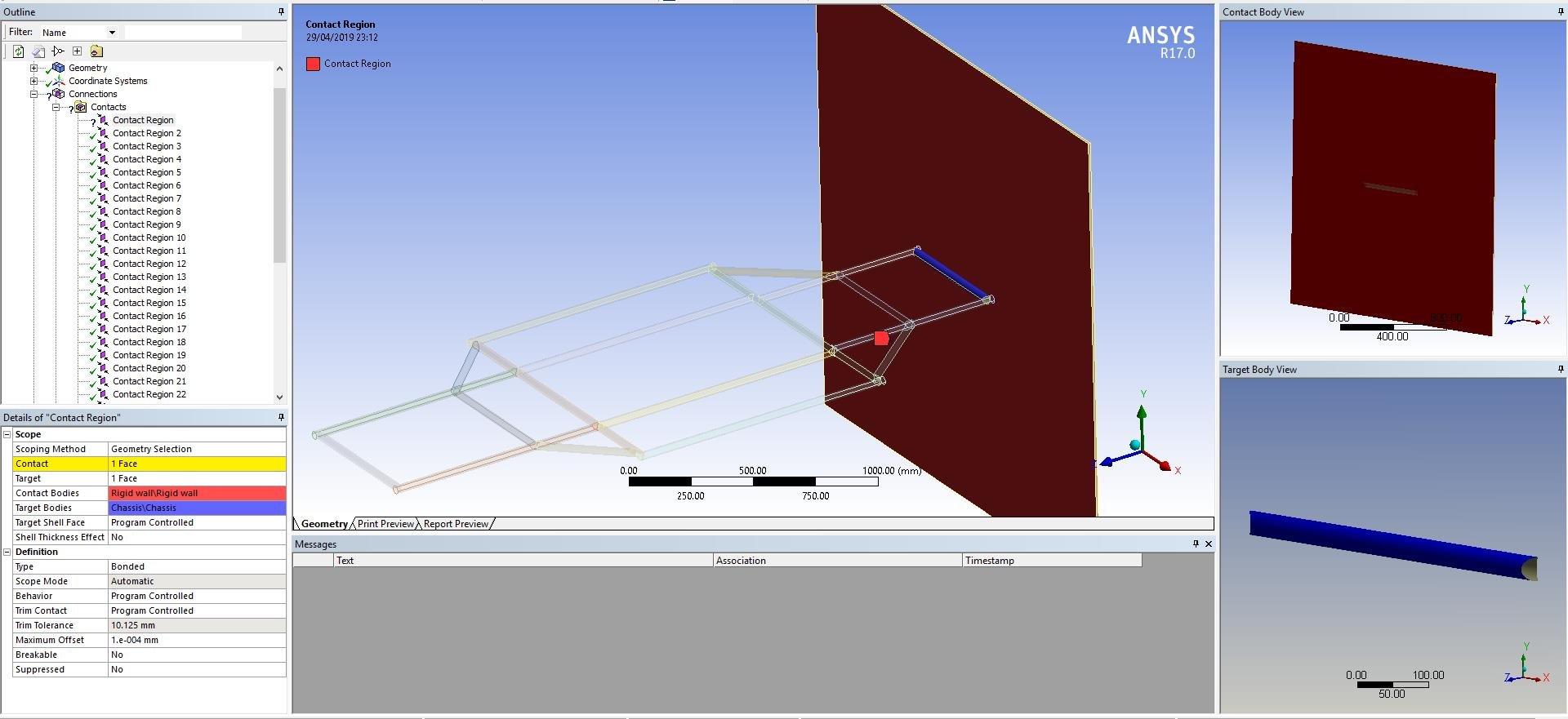
      I have come across the 'Share Topology' feature in Spaceclaim. is this something I coudl be using instead of definig the conacts manually (or generating them automatically) 

    • peteroznewman
      Subscriber

      Yes, you can try Share Topology to connect edges that touch faces.

    • RDelaCourt
      Subscriber

      Hi Peter, I made some progress on the model, I had done a terrible job with the trim feature and as a result, a lot of very small offcuts of surface area were floating about within the model ( I #m guessing this is why you had a difficult time trying to analyse the mesh when you a checked my models a couple of days ago.


      I have taken my time with the build this time and the surface/geometry are much better than before. I can get every thing to mesh and have defined the boundary conditions. 


      However now I cant run the solver. I get the error message "A general failure occurred during the solution process".  I think that its failing with the geometry Could my issue be because I have to take a different approach now that I have surfaces as opposed to solids (do I need to define shell elements within the model).


      I have attached the file if you are able to have a look. 


    • peteroznewman
      Subscriber

      If you are having trouble attaching the file because the size > 120 MB, Clear the mesh, save and archive to get a smaller file.

    • RDelaCourt
      Subscriber

      Not sure what happened there.


      Here you go.

    • peteroznewman
      Subscriber

      One mistake in your model, you only picked one body to have an initial velocity.  All the bodies (except the wall) should be picked to have an initial velocity.


    • RDelaCourt
      Subscriber

      Yes, I was aware of this and for most of my studies I have selected every part of the chassis.


      Do you think this is an issue of mesh rather than geometry? I really cannot wrap my head around this.

    • peteroznewman
      Subscriber

      I downloaded your model, changed the Initial Velocity to the entire frame and set the Maximum Energy Error to 10 and it ran for the entire 0.02 s time with no errors.

    • RDelaCourt
      Subscriber

      Right! Thank you Peter, like I said before. I am a new user to Ansys so there is obviously a lot I need to learn.


      No doubt I will be coming back at some point soon but for the moment at least, thank you for your help.

    • RDelaCourt
      Subscriber

      In regards to the geometry, I took the chassis that I constructed using weldments then within the same part created midsurfaces on the geometry. saved the part as a step file. In the step file I deleted all of the solids and saved again. Inserted the step file into a new assembly along with the wall surface and saved the assembly as a part file as opposed to an assembly opting for the option to only save surfaces and exclude bodies.


      Still had to tidy up the geometry when I imported into Spaceclaim, but it did the job nonetheless. 

    • peteroznewman
      Subscriber

      Okay, please mark the post that best answered your question with Is Solution and this Discussion will be considered Solved.

Viewing 21 reply threads
  • The topic ‘Issues with Solidworks model in ANSYS’ is closed to new replies.