TAGGED: #fluent-#cfd-#ansys
-
-
January 24, 2024 at 10:52 am
Viktor Millet
SubscriberHello ANSYS community,
I am facing difficulties in simulating a 3D Pitot tube placed inside an enclosure in ANSYS Fluent. The goal is to pass fluid at a certain velocity and pressure through the enclosure, then calculate the velocity inside the Pitot tube using the various pressure ports, in order to compare it with the introduced velocity in the enclosure.
However, I am encountering two major problems:
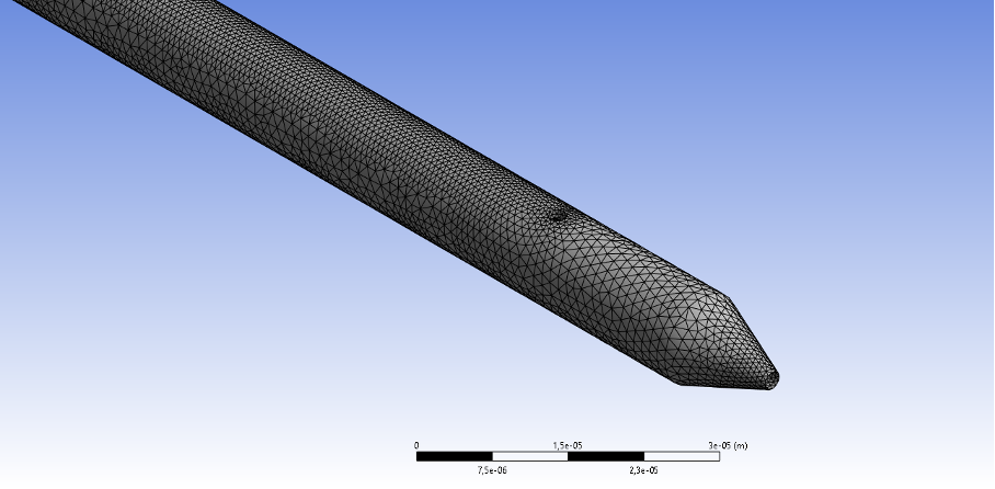
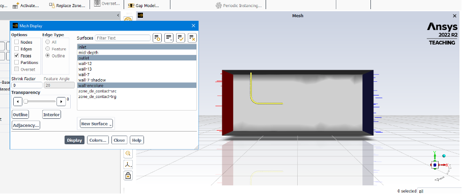
Excessive creation of walls during meshing:
- When generating the mesh, I end up with a large number of walls, complicating the modeling of flow inside the enclosure and the Pitot tube. These walls seem to interfere with the correct representation of the flow.
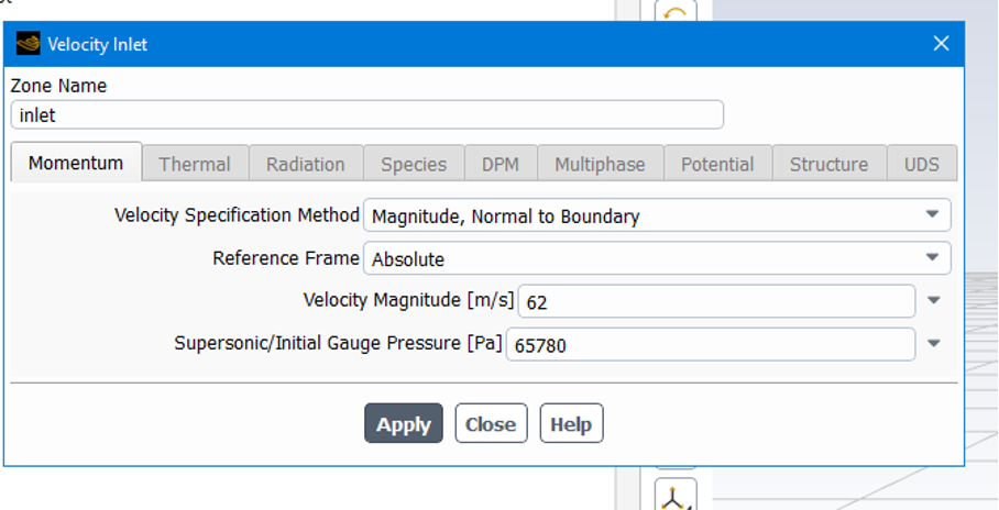
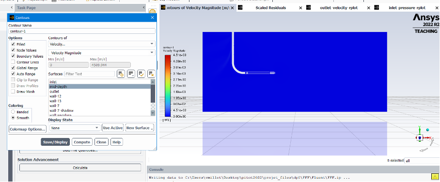
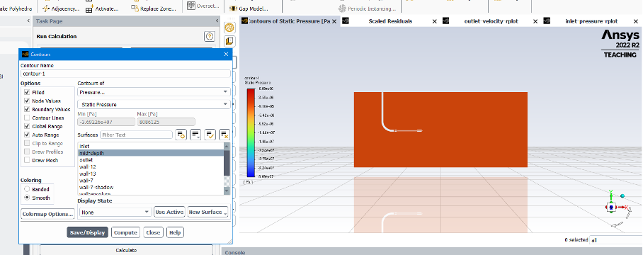
No visualized fluid movement during simulation:
- After launching the simulation, I do not visualize any fluid movement inside the enclosure. This indicates a problem with the simulation or the definition of boundary conditions.
I have tried modeling the enclosure with a fluid-filled box as well as using the enclosure tool, but the results are not satisfactory.
My specific questions are:
- How can I resolve the issue of the numerous walls generated during meshing?
- Why am I unable to visualize fluid movement inside the enclosure during the simulation?
-
January 24, 2024 at 11:19 am
Rob
Forum ModeratorWithout images showing what you've got all I can do is refer you to the training materials in Learning.Â
-
January 24, 2024 at 12:58 pm
Viktor Millet
SubscriberThank you for your response.
I understand that visual aids would be beneficial for a more accurate assessment. Here are images representing the key aspects of my simulation setup:
Mesh and Geometry:
- Image showing the mesh of the enclosure and Pitot tube.
Fluent Configuration:
- Screenshots illustrating the Fluent setup, including boundary conditions, fluid properties, and any relevant parameters.
Simulation Results:
- Snapshot of the simulation results, particularly focusing on the mid-depth plane to showcase any fluid movement or lack thereof.
I hope these images provide a clearer picture of my simulation setup. Your guidance and insights based on these visuals will be highly appreciated.
Best regards,
-
January 24, 2024 at 1:08 pm
Rob
Forum ModeratorGiven the velocity range is 0 to around 4500m/s the solution isn't good. Have a more careful look at cell quality, and then resolution in the pitot. Is the probe really 7.5microns across?Â
-
- The topic ‘Issues with simulating a 3D Pitot tube inside an enclosure’ is closed to new replies.
- How do I get my hands on Ansys Rocky DEM
- Script Error
- Unburnt Hydrocarbons contour in ANSYS FORTE for sector mesh
- convergence issue for transonic flow
- Facing trouble regarding setting up boundary conditions for SOEC Modeling
- Point exception in erosion calculation
- Errors with multi-connected bodies using AQWA
- Script Error Ansys
-
2432
-
930
-
599
-
591
-
569
© 2025 Copyright ANSYS, Inc. All rights reserved.