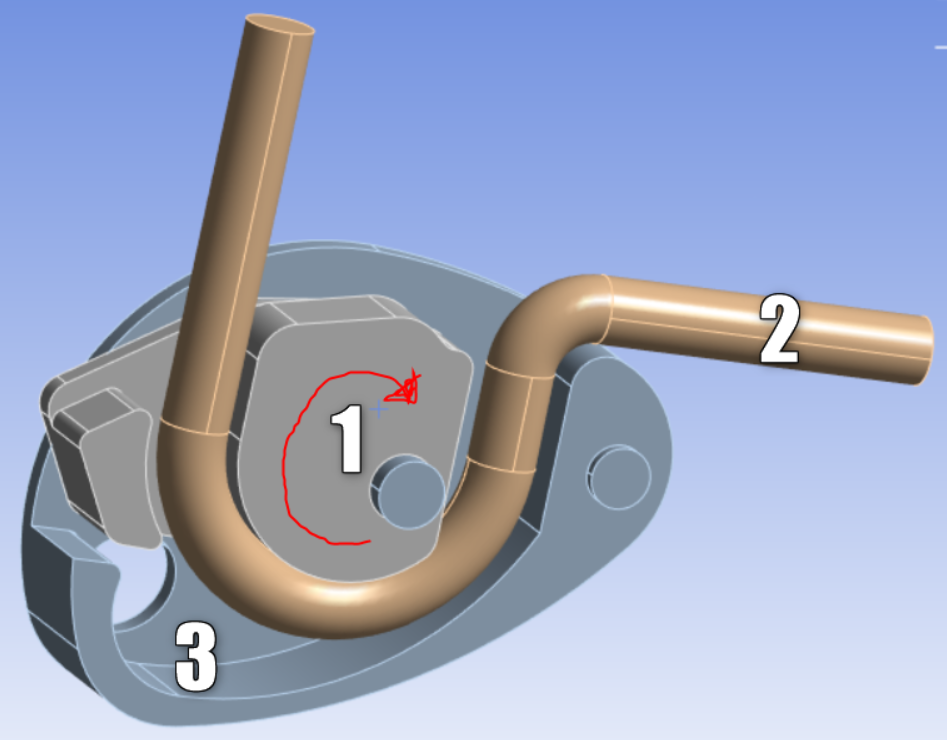
There are most likely some geometry problems with some face boundaries of that body. For many of the errors you should be able to right click on the message to "Show Problematic Geometry." Don't pay attention so much to the red vertices it shows as much as the green face. Zoom in close and scan the boundary to that face.
You may just need to set some smaller mesh sizes in the problem location such as an edge sizing. Or maybe you need to use a larger defeature tolerance to "walk" across a problem or turn on defeaturing if it's not on. If none of those work, you'll need to go back to the CAD modeler to fix the geometry once you determine the exact problem. Did you go through SpaceClaim or DesignModeler? Did you set up shared topology? Sharing topology can cause some errors if you perform the sharing and then do further modeling changes wthout first removing the sharing.
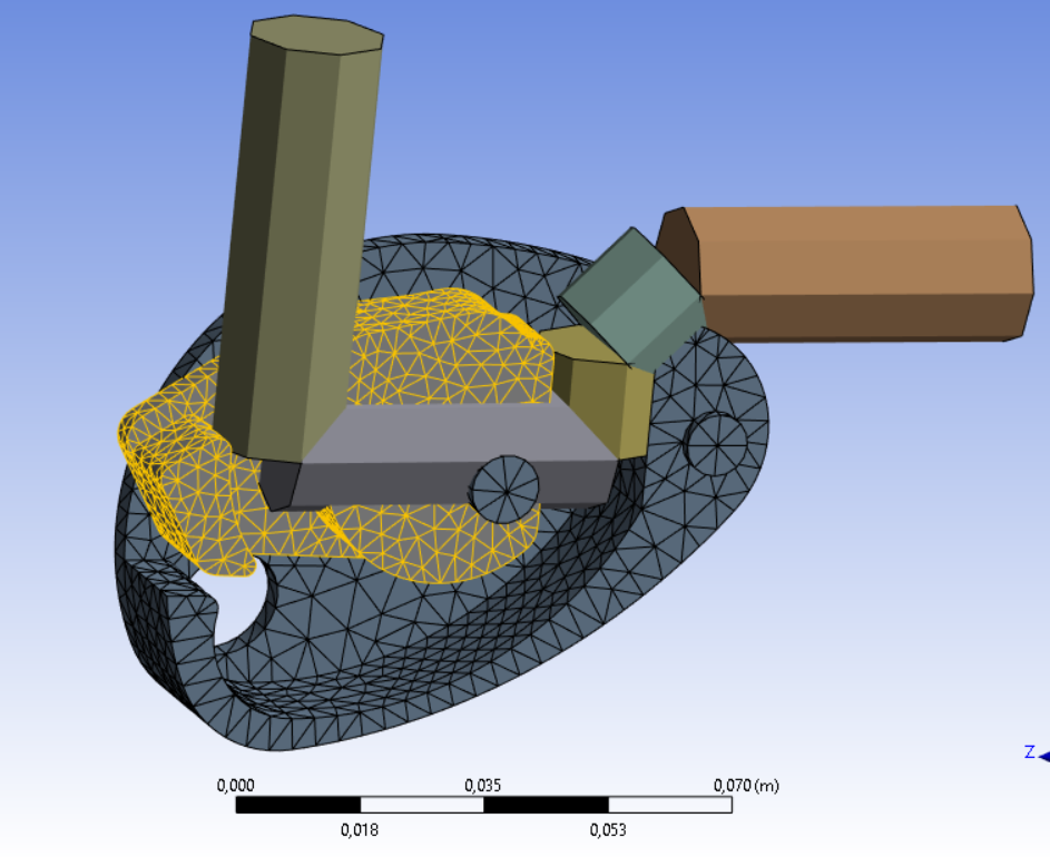
For the rope, the elements are much too coarse. Create an edge sizing under mesh controls and select the edges of the rope. A body sizing would probably also work.
For initial stress/strain on the rope, I dicussed the method in the following forum post and included a command snippet to set an initial stress:
/forum/forums/topic/how-to-model-a-rope-in-ansys-for-a-mechanical-analysis
This just sets an initial stress to put the rope in tension, so that it can solve in a static structural analysis. You would use it in the first load step and deactivate it in the second load step and others. Your analysis can develop the correct stress/strain throughout the rope over time after you deactivate the initial stress/strain. Or are you trying continue a previous analysis so that you want to set a varying stress/strain over the entire rope? This can probably be done with the inistate command also with a table. But workbench has an "External Data" system you can use to set initial stress or strain at each xyz location of the cable or at exact node numbers if a previous analysis was done with the exact same mesh.