TAGGED: combin39, force-displacement, nonlinear, springs
-
-
June 9, 2021 at 11:02 am
MickMack
SubscriberHi,
I am developing a model of a modular building, the modules are similar to shipping containers, to replicate some existing research as part of a validation process.
I am using COMBIN39 elements to model the vertical and horizontal connections between the modules as they must have axial and shear resistancee. as detailed in a previous discussion /forum/discussion/27830/how-to-create-a-model-using-solids-and-horizonta-vertical-links#latest
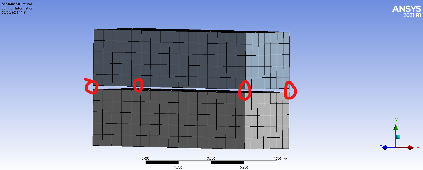
A simple model is shown below with the 4 springs highlighted
June 9, 2021 at 11:22 amJune 9, 2021 at 12:33 pmMickMack
Subscriber
Many thanks for that, i also inserted the RMORE command and i was able to solve the model.
I want to check that the springs are deforming in accordance with the force-displacement curves. I tried to insert Spring Probes but the results i am recreiving are zero, as can be seen in the snippet below.

Could you offer some advice, also in the firsst post was it correct to insert the F-D curve data into the longitudinal stiffness for the spring?
Thanks Micahael
June 9, 2021 at 12:53 pm1shan
Ansys EmployeeI don't think that is needed. Just the snippet should work. What error do you get if you do that?
Regards Ishan.
June 9, 2021 at 1:05 pmMickMack
Subscriber
Sorry, what are you referring to?
June 9, 2021 at 1:20 pmMickMack
SubscriberJune 9, 2021 at 4:52 pm1shan
Ansys EmployeeA single arbitrary value of the longitudinal stiffness should do. Once you insert the snippet it gets modified. Instead of pressure, could you fix the lower surface of lower block (which I suppose you have already done) and apply a 2 mm displacement in the Y axis (fix X and Z) to the upper surface of upper block? Also change the 'applied by' spring setting to direct attachment. Now could you check using the spring probe.
Regards Ishan.
June 9, 2021 at 9:26 pmMickMack
Subscriber
I have done everything as per your instruction but the probe still does not show anything, i will detail below with snippets.
Regards Michael
I change the Longitudinal stiffness to a single arbitrary value and changed the spring setting 'applied by' in both Reference and Mobile to direct attachment. As shown below.

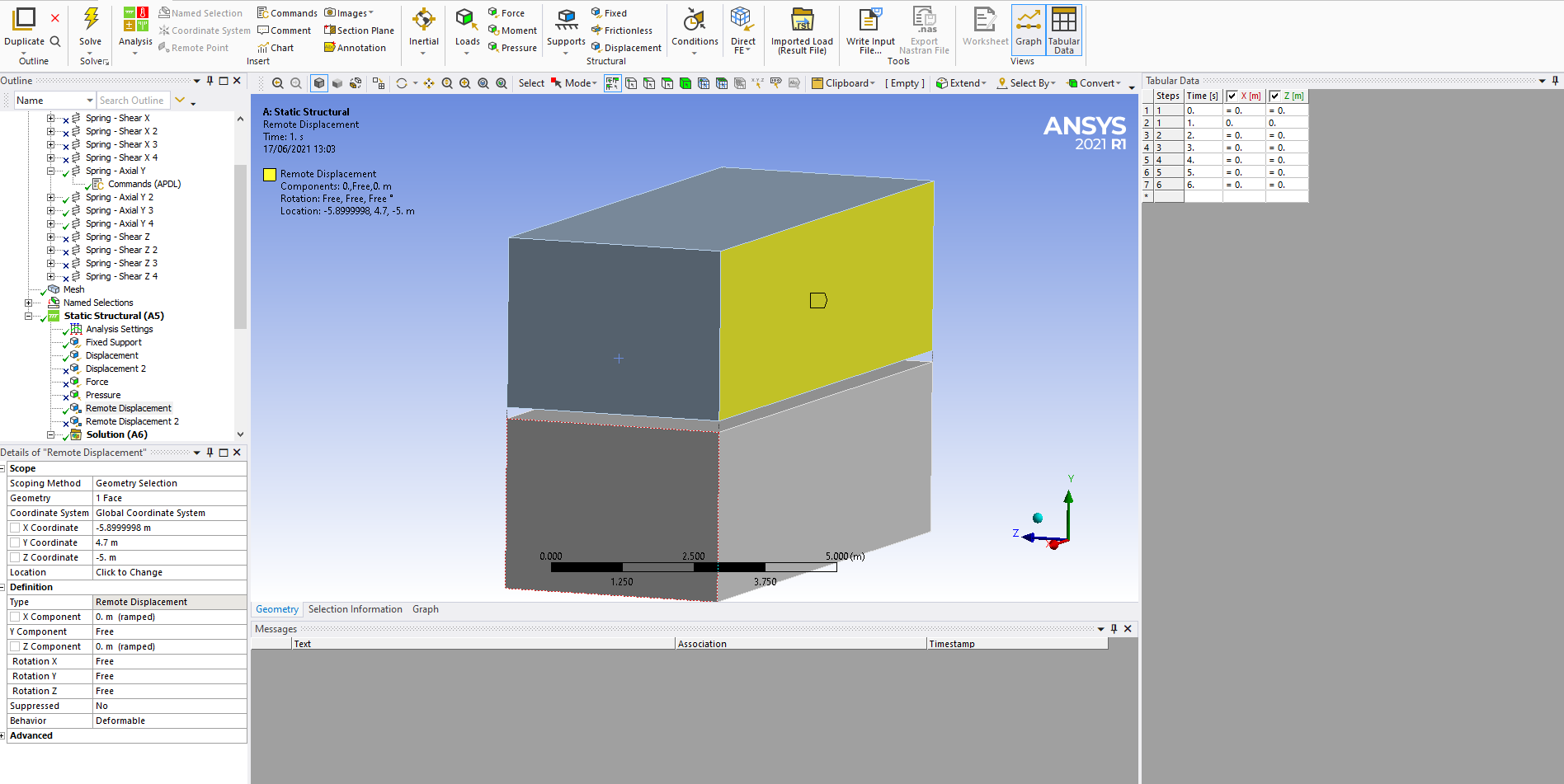
The bottom 4 vertices of the lower block fixed. I have applied a 2mm displacement to the top surface of the top block, and this has been sucessfully verified with the total deformation.

As shown above at each corner there are 3 springs, in the X, Y and Z orientation. X and Z are subject to shear and Y is axial. Hence i have 3 spring probes for each DOF at the same corner. All 3 probes are showing zero response, the Y probe is shown below.

June 10, 2021 at 6:01 am1shan
Ansys EmployeePlease use the same units for the command snippet which mechanical uses. I see a difference between both in your setup. This might be the reason.
Regards Ishan.
June 10, 2021 at 7:51 amMickMack
Subscriber
Thanks for getting back to me so quickly.
The units in the command snippet for the force-displacement curve were in ,mm+Newtons, as per the youtube video tutorial but i have now changed thess to ,metres+Newtons.
Unfortunatley the probes are still only showing values of zero. I have also turned on all output controls but this has not worked.
Is there any other settings that could be affecting this?
Regards Michael
June 14, 2021 at 9:03 amMickMack
Subscriber
I still have not resolved the issues with the beam probes.
To check if the Springs are transmitting force appropriately to the lower module i added a lateral displacement to the upper module and compared this to the previous case which only had a vertical displacement.
The reactions certainly did change as you can see in the images below, but the probes are still reporting zero results.
Any assistance would be great.
Thanks Michael


June 14, 2021 at 2:56 pmMickMack
SubscriberHi @1shan Still trying to progress this, with no joy
Is there any issue i wonder with having 3 springs at each corner?
June 14, 2021 at 4:32 pmMickMack
Subscriber
When i examine the straine of the modules the response is consistant with what i would expect from functioning springs, as shown in the image below. The force is applied at an angle.

In the force-displacement diagram each spring should displace 2mm, subject to a load of 300kN. As there are four springs i have mutilplied this by a factor of four and applied ut as a pressure on the roof of the top module 1200kN/(10m x 4m) = 30kN/m2 or 30000Pa.
As you can see in the snippet below the deformation is only 1.3476mm under this load

June 15, 2021 at 1:02 pmMickMack
SubscriberHi Can anyone help me with the spring probes, please?
They are showing zero for all values, as discussed above.
Thanks Michael
June 15, 2021 at 1:11 pmErKo
Ansys EmployeeHi
I have never used them like that so do not know - one thing to look is the result summary, find the combin elements and look at say the force in them, perhaps that will give something if they are in there and you find them.
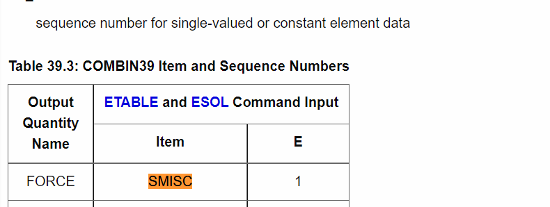
Also we can use a udr, scoped to the combin39 element and smisc1 is the force output from that element.

June 15, 2021 at 5:07 pmMickMack
Subscriber
Thanks for any assistance you can provide. I checked the result summary and all the data is reading zero for the springs as shown below.
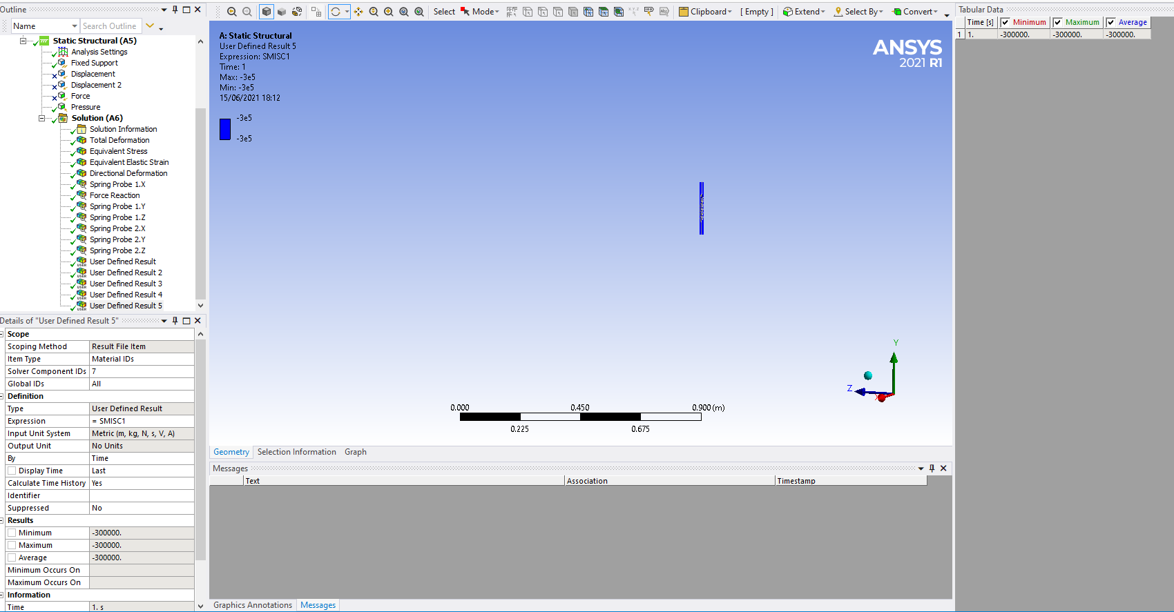
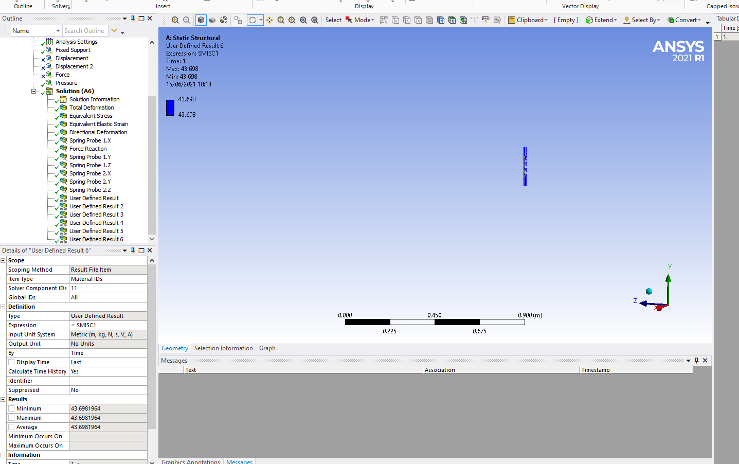
 When i inputed the user result for SMISC1 there are results as shown below

As you stated this is for force as shown below but obviously is not showing anything in the probe. Also the force in the spring in the y-direction is correct as shown (300000N) in the first snippet of results below with shome shear force apparent in both the X and Z directions, -640.848N and 43.698N respectively.

June 17, 2021 at 10:28 amMickMack
SubscriberIn my attempt to resolve this problem i have created a model of the tutorial presented in this video (https://www.youtube.com/watch?v=NN3Xf56jc0c&t=294s). As can be seen in the snippets below i have replicated this tutorial successfully and the spring probe results are consistant with those in the video.
From the spring probe results i can verify that the non-linear force-displacement data inserted with the command, is operating correctly, ie '-60,-100,' when it is displaced negative 60mm at time step 2 the force is -100N. This is the verification i need to achieve in my own model.
Any adiveice would be appreciated.
Michael
 Force Reaction results provided below also.

June 17, 2021 at 12:26 pmMickMack
SubscriberHi In my own model i have introduced some time steps to reflect the process used in the youtube video, but it made no difference.
Next i supressed the shear springs in the (x and z direction) to test if using 3 springs made any difference. Please note a remote displacement was then required to restrain the top module in the x and z directions. The supression of the shear springs still made no difference the Spring Probe did not have any data. Under the SMISC1 command suggested by,above the force is shown in the last snippet below. The values on the curve at time steps 3 and 5 are near the expected values but the final time step is significantly different at approx 50%. Excluding the outlier at time step 6, the shape of the force time curve in the last snippet is approximately what would be accepted based on the data inputted in the commpand snippet.


June 17, 2021 at 7:35 pmMickMack
Subscriberand Thankfully i have made some progress with this issue.
I created a 2nd model comparable to the simple model in the you tube video, shown below, but i changed the springs to KEYOPT 3 (1), 3(2) and 3(3), similar to my original model. Hence i also required three springs on each corner for each DOF.
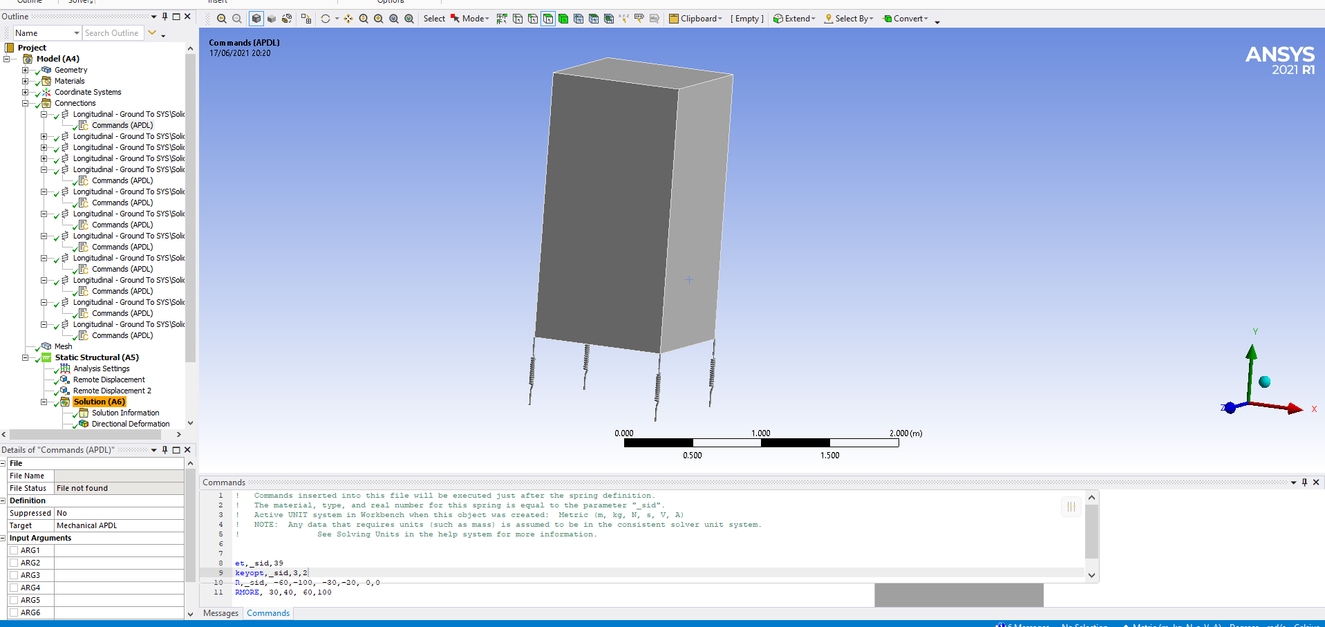 I used the F-D curve data from the youtube video, so the force in the springs would be comparable to the replica of the youtube video using KEYOPT 4(1). The command code is shown at the bottom of the snippet below. Again for whatever reason the spring probes have shown zero for all values.
However when i create the UDR smisc1 for the spring in the y-axis the force-time curve is almost identical to the results from the spring probe in the youtube replica model using spring KEYOPT 4(1). i Iinclude both graphs below.


The stretch in the spring is almost the exact same as the displacement, as shown below when using the UDR NMISC1.

Is there any reasons the results being produced are slightly different when produced with the previously stated UDR's?
I will now examine why my model was producing an outlier result at step 6, detailed in the previous post.
Any further advice would be appreciated.
June 18, 2021 at 10:22 amMickMack
Subscriberand
The issue is now with the outlier force result mentioned above, which occured at a displacement of 0.0025m in my own model, Alem_01.
To check the F-D curve data, i created a third model based on the yotube video, called tutorial_03. As discussed in previous post, this model was validated against the results in the youtube video. Therefore it is reliable, thus i only changed the force-displacement data in the command snippet to what i require in my own model as shown below. The results from tutorial_03 are producing a similar error to the results from my own model Alem_01, as presented in the table below. Please note the actual force values are in red.
The error at a displacement of 0.0025m is consistant between the two models, 675kN and 611kN respictively, but these values are only about half of the inputted force value of 1300kN.
Could anyone advise why this may be occurring? Is it to do with the change in displacement from 0.002 to 0.0025m?
Any help would be great.


June 18, 2021 at 10:51 amMickMack
Subscriberand
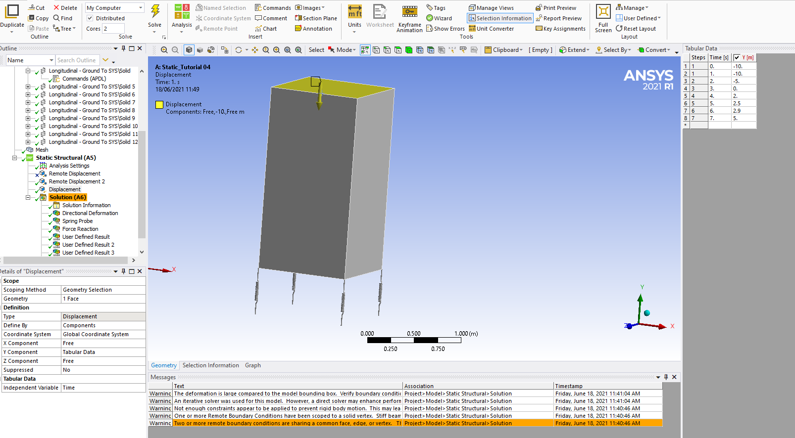
I have discovered that the issue appears to be with the magnitude of the displacement. I increased the values of displacement by a factor of 1000, and create a new model tutorial_04. The force results in the spring are now correct as presented in the table below.
 Are you aware of anything that may have caused this issue and ideally how to overcome it.
Thanks Michael
P.S. Snippet of REVISED displacement and REVISED APDL command below

June 21, 2021 at 1:12 pmMickMack
SubscriberHi
If anyone can offer some advice on this issue i would be greatful.
It appears that the COMBIN39 element is sensitive to steep F-D curve data when KEYOPT 3 is used. I have tested KEYOPT 4 and the results have been unaffected.
The element description notes that segments tending towards vertical should be avoided, see snippet below. I have considered this and considerably softened the gradient of the curve but i am still getting incorrect force results in the spring. I include two tables below tutorial_09 is the simple object with four springs as shown previously and Alem_01 is my model of two vertically stacked modules. Please note that the force diverges significantly in my model and appears to be unpredictable, as similar F-D curves are used in both examples and in compression and tension (highlighted in red).
I would be grateful for any assistance in understanding what is happening or any alternative way of achieving what i want.
Thank you Michael


June 23, 2021 at 9:11 amMickMack
SubscriberHi The issue with incorrect force results being generated by the spring was due to the displacement being applied to the top of the solid, and deformation being induced in the solid. Therefore the displacement applied to the top of the solid was not the displacement in the spring. To remedy this i applied the displacement to the bottom of the solid. Increaseing the youngs modulus of the material and hence the stiffness would also work.
I have included a table below to demonstrate the changes.

The other outstanding issue of the Spring Probe has not being resolved.
Viewing 22 reply threads- The topic ‘Issues using COMBIN39 elements’ is closed to new replies.
Innovation SpaceTrending discussionsTop Contributors-
4597
-
1500
-
1386
-
1209
-
1021
Top Rated Tags© 2025 Copyright ANSYS, Inc. All rights reserved.
Ansys does not support the usage of unauthorized Ansys software. Please visit www.ansys.com to obtain an official distribution.
-
The Ansys Learning Forum is a public forum. You are prohibited from providing (i) information that is confidential to You, your employer, or any third party, (ii) Personal Data or individually identifiable health information, (iii) any information that is U.S. Government Classified, Controlled Unclassified Information, International Traffic in Arms Regulators (ITAR) or Export Administration Regulators (EAR) controlled or otherwise have been determined by the United States Government or by a foreign government to require protection against unauthorized disclosure for reasons of national security, or (iv) topics or information restricted by the People's Republic of China data protection and privacy laws.

