Hi there, I need help with the issues i have been struggling for the past few weeks. I am modelling a quarter model of a straight steel pipe with corrosion defects in ANSYS Mechanical (Transient Structural). Internal pressure and axial tensile loading are applied simultaneously (ramped over time).
To remove rigid body motion, I first fixed a small number of nodes at the outer pipe body, but this caused severe local element distortion (“element turning inside out”) and convergence failure before the von Mises stress reaches the pipe UTS at the corrosion defect region.
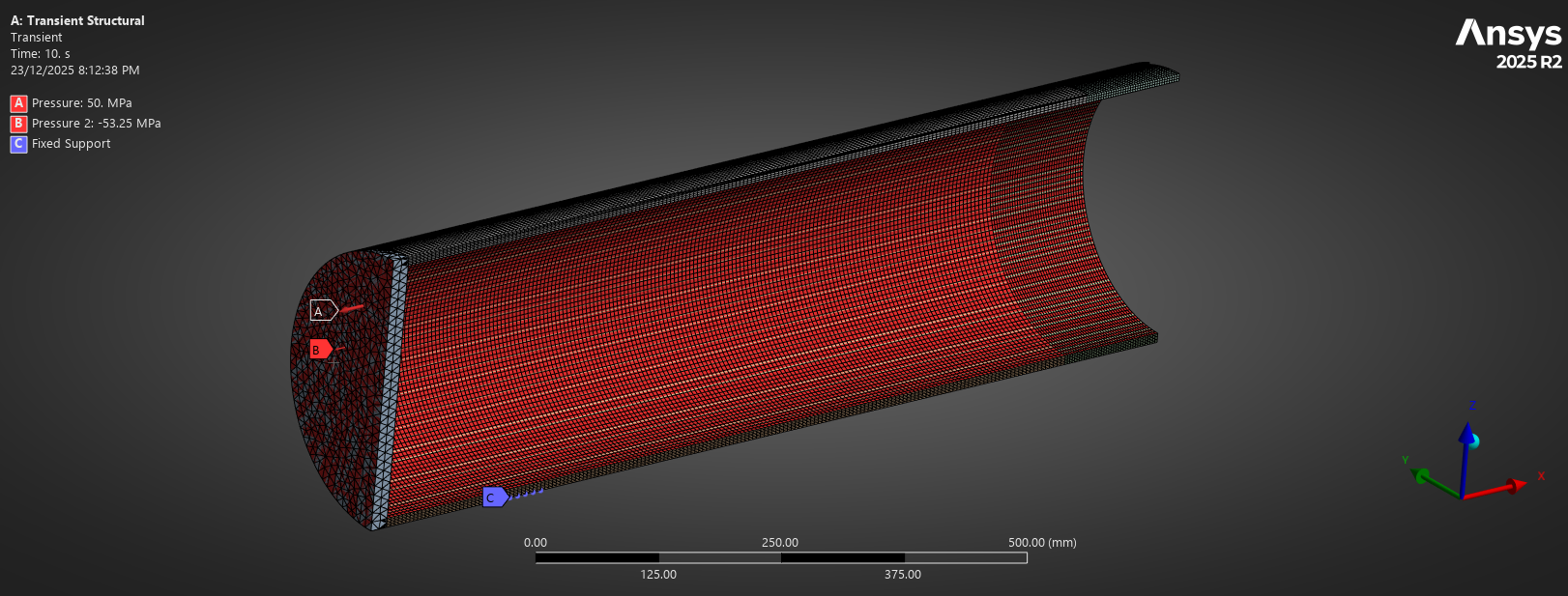
I then tried applying a Fixed Support at the centre of the end cap (the end cap is intended to act as a rigid region and should not deform). However, when I use this constraint, the axial tensile load does not seem to be properly transferred into the pipe body. During post-processing, the stress in the pipe body remains almost constant while the axial tensile load is ramping. I have attached images of the setup and loading history.

Question:
Since i want to analyse pipe failure pressure due to internal pressure and external axial tension, what is the recommended way to constrain a pressurised pipe model to prevent rigid body motion without suppressing axial load transfer or causing element distortion?


