If it helps, the code is copy pasted below.
switchtolayout;
deleteall;
###Parameters defining waveguide shape##
#Quick notes
#Distances in meters!
#Time in seconds!
#break;
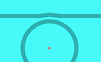
#Coupling region Parameters
SectorAngle=10;#Defines the full arc of the pulley in both directions
#away from the ring at this angle
#Combined Properties
gap=800e-9;#Waveguide-Ring Gap
height=400e-9;#Waveguide heights
base_width=1600e-9;#Waveguide width
Sidewall=60;
Cladding=0;#Set 0 for no cladding, 1 for cladding
TFLN_Height=600e-9-height;
#Ring Properties
radius=100e-6;#Radius of Ring
Ring_height=height;#Waveguide heights
Ring_width=base_width;#Waveguide width
###Parameters defining simulation##
#Distances between structure and BCs
x_sep=5e-6;
y_sep=10e-6;
z_sep=1e-6;
time=5000e-15;
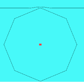
#Bezier coefficients for ideal ring
#https://spencermortensen.com/articles/bezier-circle/
BezierA=1.00005519;
BezierB=0.55342686;
BezierC=0.99873585;
#Defining arc with Bezzier
#https://stackoverflow.com/questions/734076/how-to-best-approximate-a-geometrical-arc-with-a-bezier-curve
SectorAngle2=SectorAngle;
SectorAngle=SectorAngle*(pi/180);
#Start and end points of circle
point=radius+gap+base_width/2+Ring_width/2;
x1=0;
y1=point;
x4=point*sin(SectorAngle);
y4=point*cos(SectorAngle);
xc=0;
yc=0;
ax = x1 - xc;
ay = y1 - yc;
bx = x4 - xc;
by = y4 - yc;
q1 = ax * ax + ay * ay;
q2 = q1 + ax * bx + ay * by;
k2 = (4/3) * (ax * by - ay * bx) / (sqrt(2 * q1 * q2) + q2);
x2 = xc + ax - k2 * ay;
y2 = yc + ay + k2 * ax;
x3 = xc + bx + k2 * by;
y3 = yc + by - k2 * bx;
##Start Building Structure and Simulation!##
#This is for the ring resonator
#Adds bus waveguide
addwaveguide;
set("name","+bus coupling");
set("poles",[x1, y1 ;x2, y2; x3, y3 ;x4, y4 ]);
set("base angle",Sidewall);
set("base height",height);
set("base width",base_width);
set("x",0);
set("y",0);
addwaveguide;
set("name","-bus coupling");
set("poles",[-x1, y1 ;-x2, y2; -x3, y3 ;-x4, y4 ]);
set("base angle",Sidewall);
set("base height",height);
set("base width",base_width);
set("x",0);
set("y",0);
xc2=(2*radius+2*gap+base_width+Ring_width)*sin(SectorAngle);
yc2=(2*radius+2*gap+base_width+Ring_width)*cos(SectorAngle);
addwaveguide;
#?set();
set("name","+bus transition");
set("first axis","y");
set("rotation 1",180);
set("second axis","x");
set("rotation 2",180);
set("name","+bus transition");
set("poles",[x1, y1 ;x2, y2; x3, y3 ;x4, y4 ]);set("base angle",Sidewall);
set("base height",height);
set("base width",base_width);
set("x",xc2);
set("y",yc2);
addwaveguide;
#?set();
set("name","-bus transition");
set("first axis","y");
set("rotation 1",180);
set("second axis","x");
set("rotation 2",180);
set("poles",[-x1, y1 ;-x2, y2; -x3, y3 ;-x4, y4 ]);
set("base angle",Sidewall);
set("base height",height);
set("base width",base_width);
set("x",-xc2);
set("y",yc2);
addwaveguide;
#?set();
set("name","+bus straight");
set("poles",[xc2, yc2;(xc2)*20, yc2 ]);
set("base angle",Sidewall);
set("base height",height);
set("base width",base_width);
set("x",0);
set("y",-(radius+gap+base_width/2+Ring_width/2));
addwaveguide;
#?set();
set("name","-bus straight");
set("poles",[-xc2, yc2;-(xc2)*20, yc2 ]);
set("base angle",Sidewall);
set("base height",height);
set("base width",base_width);
set("x",0);
set("y",-(radius+gap+base_width/2+Ring_width/2));
#This is for the ring resonator
addwaveguide;
set("name","ring");
set("poles",[0, radius*BezierA ; radius*BezierB, radius*BezierC; radius*BezierC, radius*BezierB ;radius*BezierA,0]);
set("base angle",Sidewall);
set("base height",Ring_height);
set("base width",Ring_width);
set("x",0);
set("y",0);
copy;
#?set();
set("first axis","z");
set("rotation 1",90);
copy;
#?set();
set("first axis","z");
set("rotation 1",180);
copy;
#?set();
set("first axis","z");
set("rotation 1",270);