
-
-
September 12, 2021 at 1:29 pm
Christopher Willett
SubscriberI am trying to model a composite plate with SOLID186 layered structural elements in ANSYS Workbench - Mechanical. I wish to partition the geometry into multiple solid volumes (completed via "slice" in design modeller); however, when I partition the geometry into multiple solid bodies I am encountering an issue with element orientation when issuing commands for a layered section for each solid body via APDL commands.
I add the following commands to each solid body of the plate geometry:
ET,MATID,SOLID186
KEYOPT,MATID,3,1
KEYOPT,MATID,8,1
SECTYPE,MATID,SHELL
SECDATA,0.3E-3,MATID,0
SECDATA,0.3E-3,MATID,90
SECNUM,MATID
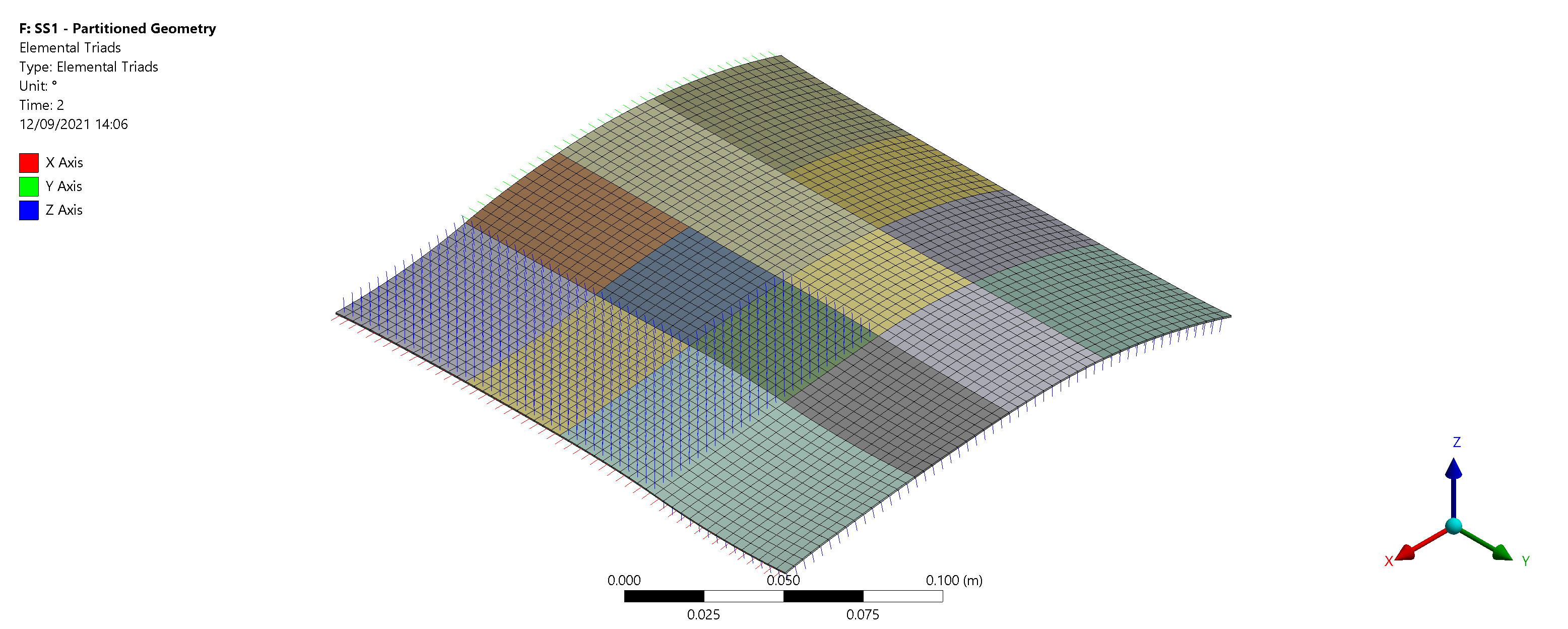
These are the resulting element triads:
September 15, 2021 at 1:44 pmGovindan Nagappan
Ansys Employee
Can you use command objects to plot the results in layer coordinate system
I see that your plot says "LAMINATE CS", but you are defining the orientations using commands. The LAMINATE CS you create in Mechanical under "coordinate system" probably doesn't match the orientation for each element defined in command object
Viewing 1 reply thread- The topic ‘Issue with element orientation when using APDL command for layered section of solid elements’ is closed to new replies.
Innovation Space Trending discussions
 Top Contributors
-
peteroznewman
 4618
4618 -
scabo
 1530
1530 -
Dennis Chen
 1386
1386 -
javat33489
 1209
1209 -
Shyam Prasad V Atri
1021
Top Rated Tags
© 2025 Copyright ANSYS, Inc. All rights reserved.
Ansys does not support the usage of unauthorized Ansys software. Please visit www.ansys.com to obtain an official distribution.
-


The Ansys Learning Forum is a public forum. You are prohibited from providing (i) information that is confidential to You, your employer, or any third party, (ii) Personal Data or individually identifiable health information, (iii) any information that is U.S. Government Classified, Controlled Unclassified Information, International Traffic in Arms Regulators (ITAR) or Export Administration Regulators (EAR) controlled or otherwise have been determined by the United States Government or by a foreign government to require protection against unauthorized disclosure for reasons of national security, or (iv) topics or information restricted by the People's Republic of China data protection and privacy laws.


