-
-
November 20, 2024 at 6:06 am
z5456415
SubscriberHi all,
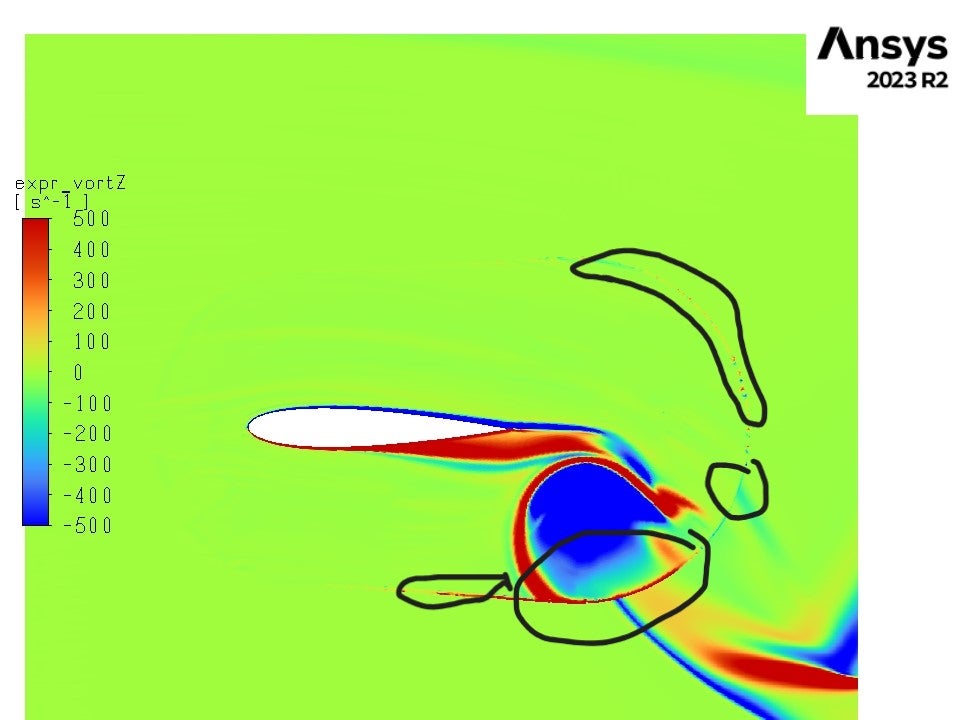
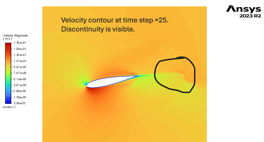
I am encountering an issue with contour plots for a pitching airfoil simulation (using a dynamic rotating mesh). The contour shows a discontinuity between the dynamic mesh zone and the background mesh. Please refer to the attached image for clarity.
Additionally, the contour plot displays the edge of the dynamic mesh zone, even though I did not select it when defining the contours.
Can anyone please assist me in resolving this problem? I am saving the contours at each time step by defining an animation under Solution Animations (in Calculation Activities) and exporting them as JPEG or PNG files. Would using ANSYS Ensight for postprocessing help address this issue after saving the files as HSF?
I also tried selecting only the background mesh and airfoil boundaries (excluding the dynamic mesh zone), but this created a gap (an empty region) between the airfoil boundary and the background mesh in the plot.
I need to use the dynamic mesh option for this simulation because I plan to simulate passive airfoil motion later (the current simulation shows active motion).
Any suggestions would be greatly appreciated!
Regards,
Muhammed Sadique
-
November 20, 2024 at 10:08 am
Rob
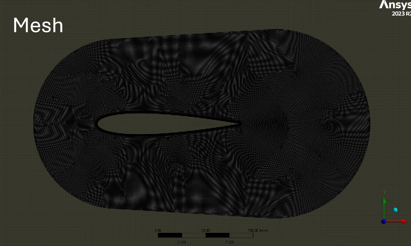
Forum ModeratorPlease can you post an image of the mesh and also velocity contour.
-
November 21, 2024 at 12:43 am
-
November 21, 2024 at 12:05 pm
Rob
Forum ModeratorOverset? How does the contact look, ie how many orphan cells are there?
-
- You must be logged in to reply to this topic.


-
1081
-
447
-
390
-
225
-
201

© 2024 Copyright ANSYS, Inc. All rights reserved.


