TAGGED: composite-material, failure, stress-singularity
-
-
December 17, 2021 at 8:25 am
Rameez_ul_Haq
SubscriberPlease observe the figure below.
December 19, 2021 at 1:30 pmRameez_ul_Haq
Subscriber,I would be grateful if you could provide your views on this one please.
December 19, 2021 at 2:06 pmpeteroznewman
SubscriberThe result shows failure. It seems to be in the skin adjacent to where the spar is bonded to the skin. If you double the skin thickness by using 12 plys instead of 6 plys, does the failure go away?
A more detailed model may help to confirm this result. Instead of bonded contact, insert solid elements to represent the adhesive material between the spar and the skin. Use Shared Topology so that the same node in the composite shell element is used by the solid adhesive element. This requires that the shell element is offset from the nodes, since the bottom (or top) ply is the one in contact with the adhesive. Use at least two layers of solid elements through the thickness of the adhesive. All elements should be linear order. Do you have the adhesive material properties?
Is the spar and skin made of the same material? Do they have the same CTE? If not, was temperature included as a load? Temperature changes from room temperature can cause large stresses in adhesively bonded assemblies of materials with differing values of CTE.
December 19, 2021 at 3:18 pmRameez_ul_Haq
Subscriberthe ply properties used in the spar and skin are the same. But ofcourse, the layup is different and the total number of ply's in both are different as well. Can you please tell the full form of CTE? Temperature was not inputted as a load.
Can you please elaborate why do you think its a failure?
What I have learned is that the sudden change in the stiffness of the structure will lead to singularities. So I was thinking that the since the bonded contact is finishing, and right adjacent to it I am seeing a highly stressed region so it might be a singularity. The reason being that the change from bonded contact to no contact is a sudden change in stiffness of the structure hence leading to a singularity. But, I need to be sure. Making these comments and judgements might be sensible, but the reality might show otherwise. That is why I wanted be absolutely certain about this situation.
Do you agree that right adjacent to the contact (linear or non-linear), I might be seeing a stress singularity? Or that is a stress concentration which will exist in reality as well? Not just this structure, but any structure.
The sudden change in stiffness will also exist in the shared topology case, and I have experienced this before in other models where, at the shared topology region, I was seeing surprisingly high stresses which I disregarded due to singularity (by making sure first that it is a singularity, like by using nodal difference and unaveraged stresses). So I don't know why you recommended shared tolology here.
Plus, why should entering a solid adhesive elements prove to be a choice for a better detailed analysis? What benefits does this bring in? I can directly connect the spar and the wing skin using shared topology, so why should I input solid adhesive elements at all? And why should the solid adhesive elements be of linear order?
December 19, 2021 at 3:38 pmpeteroznewman
SubscriberA sudden decrease in stiffness can also lead to a sudden increase in stress, which can exceed the strength of the materials. Yes, it can also be a singularity, but if elements with edge lengths larger than the thickness show failure, that is a concern. There is no point in making the elements smaller, since the stress will only increase. Making the elements larger might lower the stress at the centroid, but the unaveraged corner stress may still show failure.
The benefit of shared topology is you know exactly how each element is connected. Bonded contact is acceptable if you can see node-to-node bonds so you know exactly how each element is connected. Use MPC bonds and look at the CE plot.
One benefit of entering the solid adhesive is to determine if there is a shear failure in the adhesive bond. Say you double the thickness of the composite to eliminate the ply failure, how do you know that the load did not cause the adhesive to exceed its shear strength?
The order of the solid elements should match the order of the shell elements that have the composite properties. Aren't they linear?
December 19, 2021 at 3:53 pmRameez_ul_Haq
Subscriber,I edited just a few spelling mistakes in my previous comment and that went for moderator's approval If I decrease the element size and the stress increase (and also highly stressed region shrinks), then doesn't it imply that this region is indeed a singularity? So I am still not sure what other option can be used to determine if that is an actual failure or a singularity. Because what you wrote is also correct, that if I decrease the stiffness then the stresses are bound to increase due to lower cross sectional area. So I was thinking that decreasing the element size is the only option to check if thats a singularity or not. Other than that, there is no other way to find out if thats a failure or a singluarity. What would you say on this one?
The benefit of shared topology is you know exactly how each element is connected.
Why do I need to observe that how each element is connected? Will it play any role or help me in figuring out if thats a singularity or an actual failure?
how do you know that the load did not cause the adhesive to exceed its shear strength?
Well, that would make the analysis loose its actual meaning of conducting it, because adhesive failure is not the main concern here, but checking the main structures of any failure is the actual point. I thought that inputting an adhesive material can help me better analyse if the skin failure would be happening in reality or not, or thats just a singularity.
I inputted quadratic order for the shell elements, because, well, I had the resources of doing it Isn't quadratic better approximation than a linear order element? So if we have the resources, then why not just do it.
December 19, 2021 at 11:42 pmpeteroznewman
SubscriberListed below are two methods for joining a composite skin to a composite spar.
In one method, the two parts are cured separately, then in a secondary operation, joined together with an epoxy adhesive.
In another method, the bottom skin and front spar are co-cured so there is no additional layer of epoxy in this method.
How is the composite front spar joined to the composite bottom skin of the wing?
December 20, 2021 at 6:13 amRameez_ul_Haq
Subscriberthe composite skin and composite spar, themselves are manufactured by using dry method, separately. The adhesive are built-in into each of the plys, and no other adhesive layer is applied between the layers of plys.
However, the skin and spar are connected by layer of epoxy between them.
December 20, 2021 at 1:56 pmpeteroznewman
SubscriberLet's leave aside the fact that the epoxy layer is not in the model for now.
Failure in laminated composite panels are strongly dependent on ply orientation. You mentioned that the skin is a 6 ply layup, so that may be a [0,60,120,120,60,0] layup. Is the spar the same layup? What direction on the bottom wing skin is the 0 degree direction? Is it along the wing length? What direction on the spar flange is the 0 degree direction?
There are four basic modes of failure that occur in a laminated composite structure. These failure modes are; matrix cracking, fiber-matrix shear failure, fiber failure which could be either fiber breakage or fiber buckling, and delamination.
I use Nastran for Composite analysis so I am not familiar with the output from Ansys. You show a graph that first ply failure is predicted. Which failure mode is that? Is it strictly fiber breakage or does it include matrix cracking?
December 20, 2021 at 5:17 pmRameez_ul_Haq
Subscriber,since the skin and spar thickness is different from each other (spar being more thick). Moreover, their layup (ply stackup sequence) is also different.
I am guessing that you also have used ACP-Pre in ANSYS as well. So when I go for orthotropic elasticity in Engineering data (and also add orthtropic stress and strain limits), the necessary input properties are as follows.
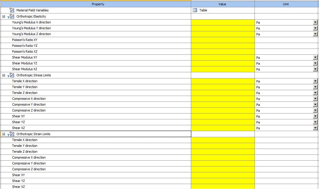 For a ply (that is available to me in physical form), I can conduct some experiments to find out the properties of that are supposed to be entered into the table above. Now here in this table, I don't see any reason why should I be entering the properties of the matrix independently. I mean in ACP pre, I can make the thickness of this ply become equal to, for example, 0.5 mm, and I can make a laminate having 4 of these plys i.e. a total of 2 mm of composite laminate. In reality, how am I gonna do it (i.e. join 4 of these plys together)? I can apply some epoxy between these plys and vaccum bag them to make them a single laminate, or maybe no need to apply the epoxy at all (if each of the plys have built-in epoxy in them) and just vaccum bag them or use autoclave. For both of these options, I don't see the need to enter the properties of epoxy/matrix separately to conduct the analysis at all. This means that the failure is not related to the matrix at all.
This implies that the failure is strictly due to fiber breakage (or a single ply breakage) and nothing else. In reality the composite can fail in any of the 4 modes that you mentioned, but my way is a simple way which neglects the occurrence of rest of the failure modes and just considers fiber breakage (ply breakage).
But my actual question is still hanging there: If I decrease the mesh element size and the failure area shrinks in the composite skin, so would that be okay to safely disregard this failure and simply declare it a singularity?
December 20, 2021 at 9:58 pmpeteroznewman
SubscriberIf you make the failure go away by reducing the mesh element size, then there would be nothing to disregard. Try it and let me know what happens.
My approach to this problem would be to understand the failure. I use the Tsai-Wu failure criterion, which is very similar to the Hoffman criterion. While these criterion are useful for predicting failure, they don't tell you the failure mode. You have to do more work to understand the failure mode, and until you understand the failure mode, it is difficult to make changes to eliminate the failure from the design.
The blank form for an orthotopic material is not useful for discussing failure modes. Below is a material ANSYS provides in the Composite Library. It is one ply of unidirectional (UD) carbon fiber in an epoxy matrix. The coordinate system for this is the X direction is the fiber direction and has the high stiffness and strength of the fiber, while the Y and Z directions are the lower stiffness and strength of the matrix. These coordinate axes are element local coordinates, not global coordinates.
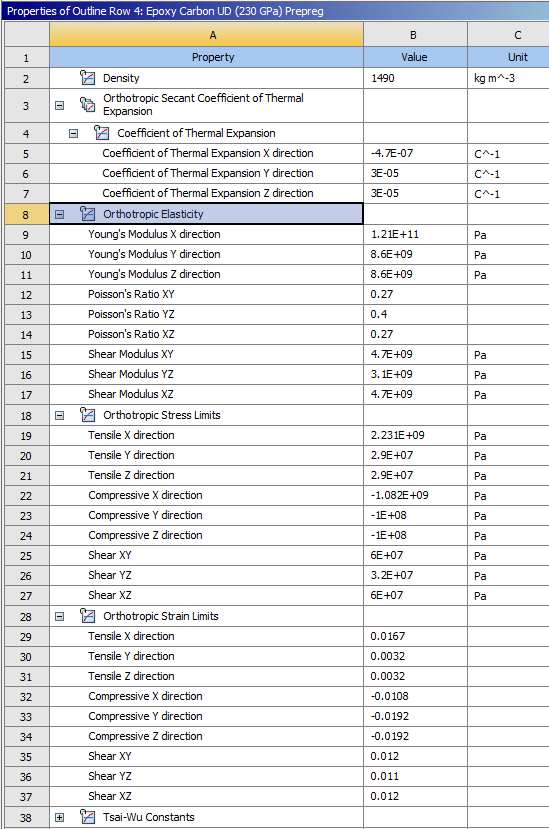 I'm not too familiar with ACP/Pre, let's say Ply 1 is at 0 degrees and that element direction lines up with Global X axis. If you plot the Normal Stress in X, and the stress exceeded the Orthotropic Tensile X direction Stress Limit, we would say that is a Tensile Fiber failure. If you plot the Normal Stress in Y, and the stress exceeded the Orthotropic Tensile Y direction Stress Limit, we would say that is a Tensile Matrix Failure.
I asked you what direction the ply on the inner surface of the wing (call it ply 1) was oriented. Since you didn't answer, I'll assume ply 1 is along the length of the wing. That is the ply that is bonded to the spar. Plot ply 1 normal stress in the chord direction and compare that with the Stress Limits in the Y direction. If the stress has exceeded the limits, then the failure mode is a matrix failure. Rotating the entire layup 90 degrees might make that failure go away, because the higher Stress Limits in the X direction would now be used.
Alternatively, if ply 1 is already aligned with the chord direction, then rotating the entire layup is not going to help.
December 21, 2021 at 9:41 amRameez_ul_Haq
Subscriber,I mean we know that the failure region (Inverse Reserve Factors greater than 1) is not gonna go away at all even if thats a singularity. But due to decrease in element size, it might shrink (i.e. still happening at the same elements and not any extra elements, but the size of it will decrease with increase IRF values).
Pardon me for not answering about the direction of ply, and yes the fiber direction (of a UD fiber) of ply 1 (bonded to the spar) is along the length of the wing. And thank you for the feedback on the ply oreintation in figuring out the failure mode.
To be honest, I haven't done a detailed analysis check to figure out if this ply is failing in the direction of fiber (X direction) or the direction of matrix (Y direction). Ofcourse, if the stresses in X direction are higher than the tensile/compressive strength of ply in that direction, then it fails in fiber breakage whereas if stresses in Y direction are higher than the tensile/compressive strength in that direction of the ply, then it fails in Matrix mode (maybe matrix cracking). This can be done easily using the sampling point tool and in the same figure that I posted for IRF of plys in my question, the stresses along the X and Y both directions can be written on the same figure. The problem is sir, I don't know how does a singularity affect the results for composite surfaces. For example, I might be seeing stresses higher in the fiber direction than its strength so I might be thinking that it is because of fiber breakage, but that might be actually a singularity. Similarly, the stresses might be higher in the matrix direction than the strength along that direction and I might be assuming that it is because of matrix failure, but that might be a result of singluarity. You understand, right, where I am going with this?
So the singularity problem is easier for an isotropic material, like I can conduct a mesh convergence study. For a composite material, near me it is not easy at all. That is why I was saying that mesh convergence near the failure region might result in the regions having IRFs greater than 1, to shrink since the mesh size has decreased. If they do, then yes its a singularity, but if they don't instead the region tends to increase, then I am sure that it is not because of singularity (no matter if the ply is failing in fiber breakage mode or matrix failure mode, and how much the stress has increased). In this case, I have to spend much more time in trying to diagnose the actual failure mode, and taking necessary measures to avoid this failure.
December 21, 2021 at 1:56 pmpeteroznewman
Subscriber"we know that the failure region (Inverse Reserve Factors greater than 1) is not gonna go away at all even if that's a singularity"
Just because there is a singularity in the model, does not mean the failure region cannot be made to go away. For the element size you have, if you change the design to reduce the stress, such as the two suggestions I gave above (rotate layup 90 degrees, double the layup), the failure region may very well disappear.
I understand your point that the failure may reappear if you make the elements small enough.
That is where experimental validation comes to the rescue. A company using composites could make composite single or double lap shear coupons to measure the strength of adhesively bonded joints planned for the design. An FEA model of that coupon can be built. A specific element size can be used in that model, and model parameters found so the model results correlate to the experimental results. You can see examples of this in the literature.
You have to do the work to eliminate the failure. That may require a far more detailed model that includes the adhesive. There are designs that require a fillet of adhesive to eliminate the singularity such as I have shown in your other thread on singularities. /forum/discussion/25878/a-couple-of-queries-about-contact-and-stresses-near-it
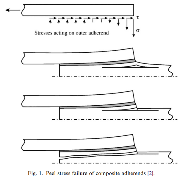
Below is an image of how a thickness discontinuity can induce a delamination failure mode in a composite panel.
 Below is a design of the plate and adhesive profile that reduces the stress at the discontinuity.
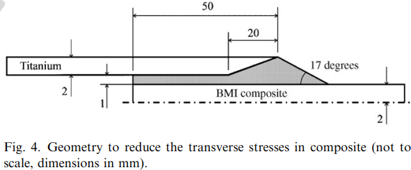 These figures are from the paper, Techniques to reduce the peel stresses in adhesive joints with composites by L.F.M. da Silva and R. D. Adams. https://www.researchgate.net/publication/313550664
Sangwook Lee wrote his PhD thesis on Failure of Laminated Composites at Thickness Discontinuities... https://thesis.library.caltech.edu/279/
The samples in that work were flat panels with a stiffener in the center of the plate, but the stiffener was co-cured with the panel, so there was no additional layer of epoxy adhesive.
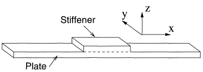 That thesis has experimental measurements of the onset of failure in samples, and a FEM to analyze stress in each ply. In the section on the Finite Element Model, he mentioned that his model has a singularity and why that was acceptable.
December 21, 2021 at 4:32 pmRameez_ul_Haq
Subscriber,I am very much perplexed to hear what you said in your first paragraph. You mean that even if those high IRFs resulting in a failure in that local region is (assume) due to singularity, but messing with the plyup or its thickness can make it go away? I am surprised to hear this because you taught me that singularity is something which cannot be avoided (if no geometric modifications are made like substituting it with a fillet, no contact change is made, etc). If I am just changing the plyup or just thickness, I just couldn't comprehend that how can that make the singularity go away (i.e. the failure region can be made to go away).
I understand your point that the failure may reappear if you make the elements small enough.
Yes, but if they are shrinking then a singularity. Instead if are expanding over more elements then a failure. If the former occurs, then no need to spend any energy in trying to figure out the failure modes whatsoever, since its a singularity. If the latter happens, then it is required. What would you say? But thats a different story that an actual failure might also happen at the region of singularity, like contact change. I don't know how to deal with this. Maybe entering an adhesive in this region, as you recommended, might be able to make me differentiate that was it actually a stress concentration (which is causing failure) or just a singularity. Your comments would be appreciated.
Also, I will check out the links you shared.
December 21, 2021 at 7:01 pmpeteroznewman
SubscriberThe material in this model has a yield strength of 250 MPa. The geometry has two singularities. The maximum stress is 350 MPa for a 0.5 mm element size. I need to change the design to eliminate the failure.
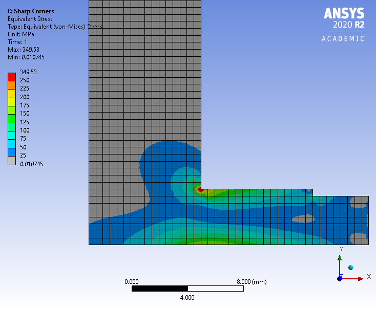 Below I have added a 2 mm fillet in the corner with high stress. The maximum stress is now 244 MPa so there is no longer a failure in this model.
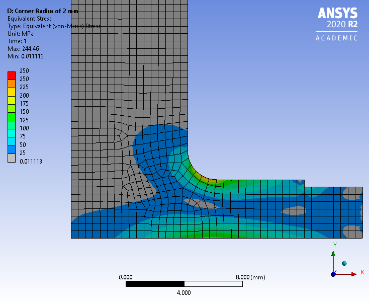 A mesh refinement study on the elements around that fillet will show that the stress goes down to 242 MPa with elements half the size then up to 245 MPa with quarter this size. If I presented the image above in a Design Review, I doubt there would be any questions about the stress at the small step.
Yes, of course if I were to refine the mesh around the small step, I could get that to become the highest stress in the model as has been done in the image below. Even if I showed the image below in a Design Review (which I wouldn't), everyone would agree that we can ignore that value of stress because it is coming from a singularity.
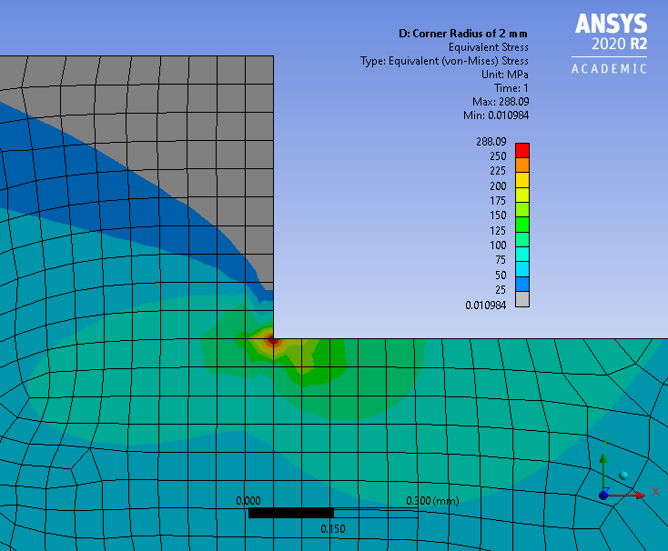 Note that while trying in eliminate the failure from the design, I may have tried a 1 mm fillet radius, eliminating the singularity, but not the failure because the corner stress was 320 MPa. I have to go to a 2 mm fillet to eliminate failure.
 There are singularities all over the model. We care about the ones that are located where the stress has exceeded the failure threshold. You have a singularity on both sides of the spar but you only circled the one side that shows failure.
After finding a location where stress is above the failure stress limits, we look for design changes that can reduce the stress below the limit or build a more detailed model of the current design that shows the stress is not actually exceeding the stress limit.
December 21, 2021 at 7:32 pmpeteroznewman
SubscriberI may have to learn ACP/Pre and ACP/Post to show more relevant examples.
December 21, 2021 at 7:50 pmRameez_ul_Haq
SubscriberExactly sir, I replace the sharp corner with a fillet, the singularity goes away. The stresses then converge. Yes, you already taught me that and I have kept it in mind since then. We put in a sharp fillet radius, the stresses would be very high. We put in a higher fillet radius, the stresses would decrease. Reason, as taught by you to me, is that the load path wouldn't just all pile up at the sharp fillet radius; instead it would get dsitributed all over the big fillet radius which results in relatively lower stress.
Well, thank you sir for having such a detailed conversation on this topic. It was very useful.
December 21, 2021 at 8:10 pmpeteroznewman
SubscriberOne point made above is that complex models have singularities all over the place and we ignore most of them.
The other point that you will struggle with, is that sometimes the singularity will be at a location where you can't ignore it, but you can investigate design changes at a constant element size to determine which ones will reduce the stress below the limit. Validation experiments that correlate measured results with FEA results at an acceptable element size means you don't have to use smaller elements.
Good luck!
Viewing 17 reply threads- The topic ‘Is this a singularity or an actual stress concentration?’ is closed to new replies.
Innovation SpaceTrending discussionsTop Contributors-
4803
-
1576
-
1386
-
1242
-
1021
Top Rated Tags© 2026 Copyright ANSYS, Inc. All rights reserved.
Ansys does not support the usage of unauthorized Ansys software. Please visit www.ansys.com to obtain an official distribution.
-
The Ansys Learning Forum is a public forum. You are prohibited from providing (i) information that is confidential to You, your employer, or any third party, (ii) Personal Data or individually identifiable health information, (iii) any information that is U.S. Government Classified, Controlled Unclassified Information, International Traffic in Arms Regulators (ITAR) or Export Administration Regulators (EAR) controlled or otherwise have been determined by the United States Government or by a foreign government to require protection against unauthorized disclosure for reasons of national security, or (iv) topics or information restricted by the People's Republic of China data protection and privacy laws.


