
TAGGED: balloon, element-distortion, error, nonlinear, structural-mechanics
-
-
March 17, 2022 at 4:09 pm
Ben_Ben
SubscriberI am currently inflating a simple cylindrical balloon (pictured below). I can only get a displacement of 1.5mm before I get errors of element distortion. Is there a way to increase the amount of displacement in static structural? Or would I have to move over to LS-Dyna?
March 18, 2022 at 2:33 ampeteroznewman
SubscriberThere are many resources on Hyperelastic material model convergence. Here is mine:
March 18, 2022 at 11:34 amSubscriberHi Peter,
My balloon is a shell181 model. In the help documentation I can't see an option for mixed formulation for 181. I added keyopt 3 = 1 for uniform reduced integration and am running it now.
I am going to try and change the balloon to a solid model and try all the steps mentioned in the video.
March 20, 2022 at 1:41 amSubscriberMixed u-P formulation only applies to solid elements, not shell elements.
March 20, 2022 at 10:21 amSubscriberThanks for the reply. I will convert my model to solid elements and try it.
Do you have any tips for shell elements or would you just recommend moving to a solid model?
March 20, 2022 at 11:35 amSubscriberWhat are the boundary conditions of the shell elements? If you used a Fixed Support, that can cause element distortion. Use a Remote Displacement, Behavior = Deformable to reduce the influence of the boundary condition on element distortion. This advice applies to both solid and shell models.
March 21, 2022 at 10:02 amSubscriberHi Peter I have a cylindrical support that has fixed axial displacement and is free radially and tangentially. How would you recommend applying the boundary condition? I can be flexible with my modelling techniques, all I need is the balloon to expand as much as possible.
Thanks Ben
March 21, 2022 at 12:09 pmSubscriberHi Ben Fixed axially is a problem because as the balloon expands it gets shorter and the axial constraint is preventing that from happening.
Use two remote displacements, Behavior = Deformable. You don't show the axial coordinate direction, but assume it is Z.
One remote displacement is scoped to the edge at one end and sets X, Y, Z and Rot Z to 0 leaving the other two free.
The other remote displacement is scoped to the edge at the other end and sets X and Y to 0 leaving the other four free.
March 21, 2022 at 1:32 pmSubscriberOk I'm going to try this now!
Currently using Cylindrical coordinates, where x is radial direction and z is the axial direction. Are the remote displacements still valid for my coordinate system?
Thanks,
Ben
March 21, 2022 at 4:09 pmSubscriberJust found that you can't set remote displacements with cylindrical coordinates so running with cartesian but X is radial and Z is axial still.
 Also for some reason the solver file is telling me I have contact elements in the model. Even though I don't. Could this be because I created the surface with SpaceClaim's midsurface tool?

March 21, 2022 at 5:13 pmSubscriberCartesian is fine for the remote displacement. The contact elements are being used to distribute the pressure over the element faces.
March 22, 2022 at 9:17 amSubscriber Hi Peter,
It's not converging past the start of the first time step. When I then switch back to cylindrical support it converges easily for the same set up. Have I set up something wrong?


 March 22, 2022 at 12:02 pmSubscriberThe Location of each Remote Displacement is wrong. They should both have X and Y coordinates of 0 if they are on the axis of the cylinder. They should have a Z coordinate for the location in Z of each edge.
The Remote Displacement has the wrong rotational constraint. It is Rot Z that should be 0 to prevent the cylinder spinning about its axis.
Reduce the Pressure to 3e-6 MPa and see if it converges.
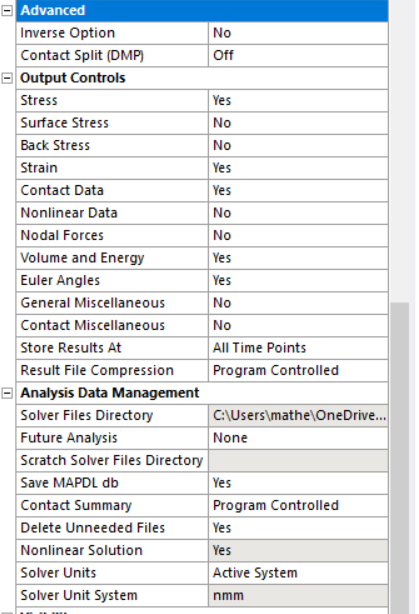
Show your Analysis Settings Details. Show the N-R Force Residual plot.
March 22, 2022 at 5:40 pmSubscriberSorted out all the changes and runs for 3e-2MPa but when I run with 8e-2 MPa (the pressure I was using with cylindrical support) it fails to converge at around 4e-2MPa.
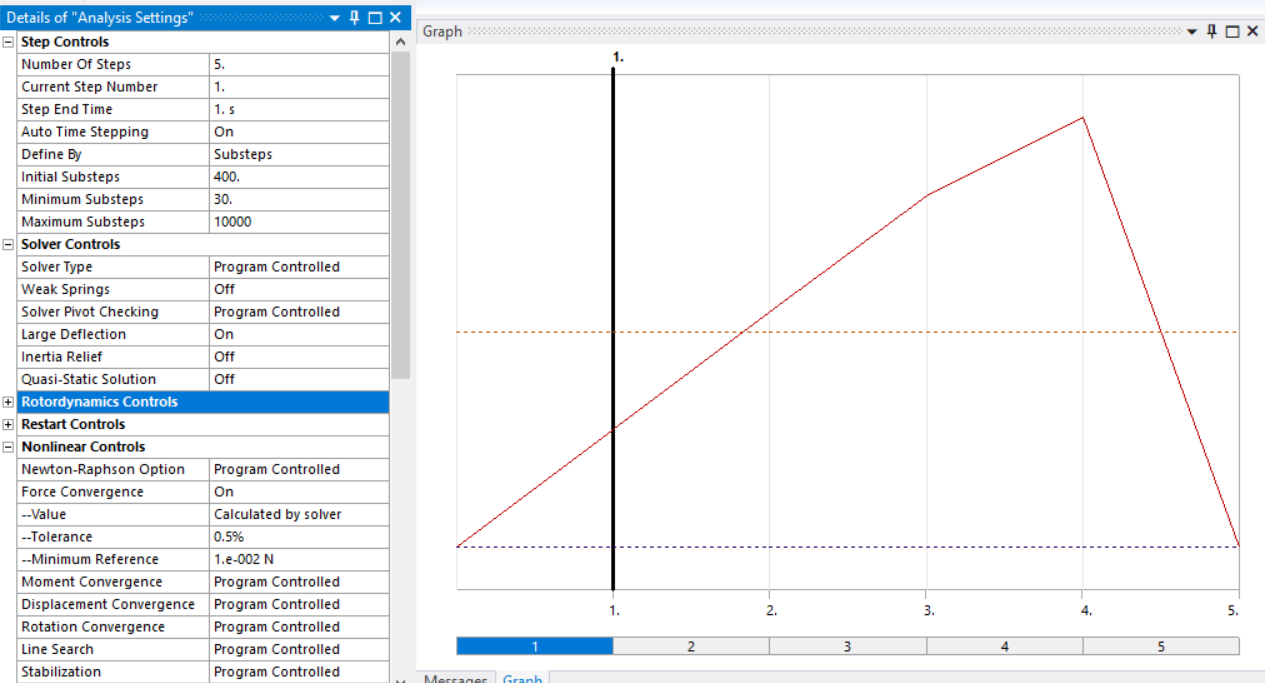
I have been running on a HPC in batch mode, I'm not sure how to produce the N-R Force Residual plot. If you could direct me on that I would be much appreciated.
March 22, 2022 at 6:05 pmSubscriberI get errors of excessive distortion

March 22, 2022 at 8:18 pmSubscriberIn Workbench, use File, Archive to create a .wbpz file and attach that to your reply. State the version of ANSYS you are using.
In Mechanical, under Analysis Settings, turn on Stabilization and use the Constant setting with the defaults. See if that helps.
March 22, 2022 at 11:44 pmSubscriberI am using Ansys 2020 R2
The stabilization allowed it to run for a longer period of time. It was just taking very small time steps, so I paused it as I was running on my local machine. Submitting it to the HPC now.
The .wbpz file was too big to attach. It is 300MB
March 22, 2022 at 11:53 pmSubscriberI cleared the result file and now the file is much smaller.
March 23, 2022 at 11:42 amSubscriberThe unconverged solution is behaving in an unexpected way. The cylinder seems to be bending rather than expanding.
 Could this indicate that the remote displacements are applied incorrectly?
March 24, 2022 at 11:06 amSubscriberDon't look at the unconverged substep, look at the last converged substep, that is something you can trust.
March 24, 2022 at 5:47 pmSubscriberWill do!
Did the .wbpz file show you anything? when I'm running it struggles to converge at around 2/5ths of the pressure I can converge when using a cylindrical support.
Can you think of any other BCs that would allow a greater expansion? Or is the remote displacement the best choice in your opinion?
March 25, 2022 at 2:03 amSubscriberWhat is your goal in applying pressure to this open-ended tube? What do you need to learn from the simulation? You call it a balloon, but it's not a balloon. A balloon has a closed ends and a smaller tube for inflation. What I can see in the open-ended tube simulation is that one open end of the balloon becomes unstable.
Close the balloon ends and you can get the inflation to 0.78 of 0.11 MPa before an error occurs.
 The error is excessive thickness change. Plot the stress in the balloon and you can see that the pressure has reached the point when the balloon pops.
 The purpose of the balloon is to push against a stent. Do you have a stent? In my experience, the first step is to deploy a bare metal stent by applying pressure directly to the inside face of the stent where the balloon would push. After you get a bare metal stent to deploy using pressure on the inside face, you can put the stent inside an artery. After you have a stent deploying in the artery, the next step is to use a balloon to push on the stent which pushes on an artery.
March 25, 2022 at 10:29 amSubscriberIf you need this balloon shape and material to support a pressure of 0.11 MPa, increase the wall thickness.
March 25, 2022 at 10:35 amSubscriberHi Peter,
Thanks for the detailed reply. I am trying to model a balloon that expands and pushes back the valves in the heart. It needs to be around 2.5mm to start with so it can fit between the 3 valves. I was then looking for it to inflate maybe 4 or more mm radially and use contact between the balloon and the heart valves to push the valves back.
In the scientific papers they model the balloon as a folded structure and then inflate it (see E to A in image below). So the balloon is effectively folded in layers so it can fit into small places and then can be inflated to a much bigger diameter as it won't be plagued by element distortion.
 But I'm not sure how to model this situation so I was seeing if I could simplify it by using a simple cylinder and inflating with a pressure. If you have any advice on modelling a folded up balloon that would be much appreciated.
I will have a look at your .wbpz file. Maybe I should try and model a more balloon like shape with closed ends.
March 25, 2022 at 11:28 amSubscriberOk sounds good. More looking for a large radial deformation so I can be flexible with wall thickness.
March 25, 2022 at 3:55 pmSubscriberResearchers doing simulations of balloons start with geometry in the shape of a circular balloon at the size it was manufactured, then use moving rigid surfaces to fold the balloon using frictional contact to simulate the folding that an actual machine with moving blades would use to fold the balloon. Then they simulate the inflation of the folded balloon.
These models tend to run in Explicit Dynamics because of the complex contact modeling required. You can't use the Mooney-Rivlin material model in Explicit Dynamics, so you will have to replace that will a material model that is supported in Explicit Dynamics.
March 27, 2022 at 12:59 pmSubscriberOk. I think I'll give the folded structure a go over next couple of weeks. For the mean time I will run your balloon geometry in my model. Thanks for all the advice over the last week. Really appreciate it.
March 27, 2022 at 1:58 pmSubscriberUpdate to my previous comment. The error I got when I linked an Explicit Dynamics analysis to your Static Structural analysis was because the Balloon material had no Density defined. Once I added a Density property, Explicit Dynamics ran with the Mooney-Rivlin material model.
March 27, 2022 at 3:21 pmSubscriberOh nice! Would it be possible to send the updated .wbpz file?
March 27, 2022 at 6:54 pmSubscriber
The thing about Explicit Dynamics is it can take a long time to compute. I can show you results from this model in 2 days!
 Pressure ramps up from 0 to 1 MPa at the end time of .010 seconds. The density of the balloon material has been set at an artificially high value to increase the time increment up to 3e-10 s.
The Mooney-Rivlin material only ran on solid elements, it did not run with shell elements. This is a 1/8 model, so the boundary conditions were very simple on the three cut planes.
 March 28, 2022 at 2:06 pmSubscriberThanks.
Will give it a go and see how it turns out. Will be good for my learning anyway.
Viewing 30 reply threads- The topic ‘Is there anyway to increase the inflation of my balloon? ELEMENT DISTORTION’ is closed to new replies.
Innovation Space Trending discussions
 Top Contributors
-
peteroznewman
 5799
5799 -
scabo
 1906
1906 -
Dennis Chen
 1420
1420 -
javat33489
 1305
1305 -
Shyam Prasad V Atri
1021
Top Rated Tags
© 2026 Copyright ANSYS, Inc. All rights reserved.
Ansys does not support the usage of unauthorized Ansys software. Please visit www.ansys.com to obtain an official distribution.
-


The Ansys Learning Forum is a public forum. You are prohibited from providing (i) information that is confidential to You, your employer, or any third party, (ii) Personal Data or individually identifiable health information, (iii) any information that is U.S. Government Classified, Controlled Unclassified Information, International Traffic in Arms Regulators (ITAR) or Export Administration Regulators (EAR) controlled or otherwise have been determined by the United States Government or by a foreign government to require protection against unauthorized disclosure for reasons of national security, or (iv) topics or information restricted by the People's Republic of China data protection and privacy laws.
