-
-
July 21, 2022 at 1:15 am
mo_911
SubscriberI am trying to use the sample files for inverse design of y-branch without making any changes to follow the steps.
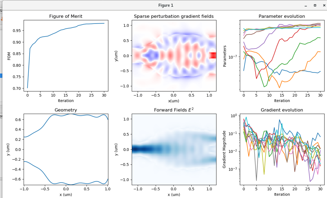
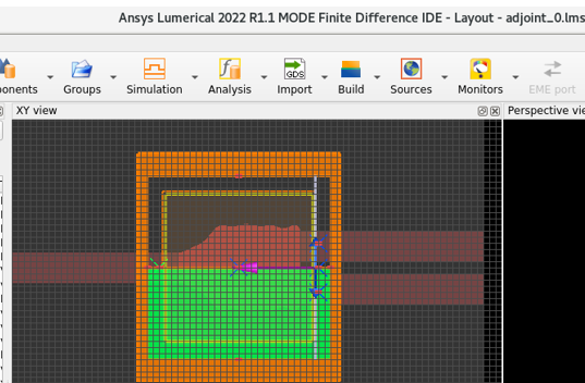
After running the 2.5D optimization, I finally got the optimized geometry in the Figure 1 and the MODE file "adjoint_0.lms" as shown below.
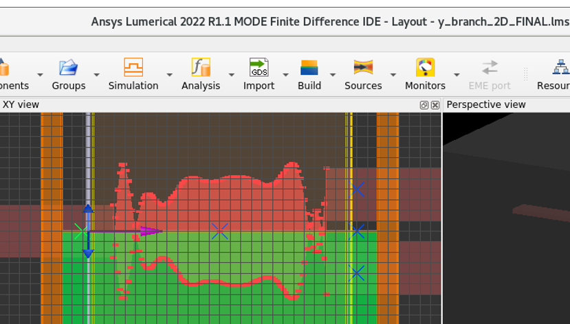
When the optimization was done, the MODE file named "y_branch_2D_FINAL.lms" showed up as shown below. However, the geometry was different from the optimized one. When I ran the 3D optimization, this geometry was used as the initial input. Thus, the 3D optimization did not work well.
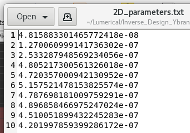
And more, the GDS file was not generated after the 2.5D optimization, though the text file named "2D_parameters.txt" was generated in the same folder as the sample files and the python files.
Thus, I would like to know
Q1. Why the 2.5D optimized geometry was not shown in y_branch_2D_FINAL.lms
Q2. Why the 2.5D optimized geometry was not used as the initial input for the 3D optimization
Q3. Why the GDS file for the 2.5D optimized geometry was not saved or exported.
Thanks
-
July 21, 2022 at 6:04 pm
mo_911
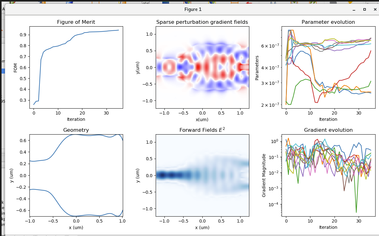
SubscriberWhen I ran the 3D optimization script, the 2.5D optimized geometry was not used as the initial input, but the geometry shown in “y_branch_2D_FINAL.lms” was used as I wrote above. Then the 3D optimization was finished after 35 itenarations. I got the results as “Figure 1” is shown below and the geometry looks good. And "3D_parameters.txt" was generated.
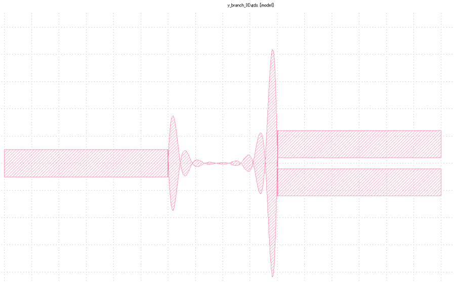
In this case, the GDS file named “y_branch_3D.gds” was successfully saved, but the geometry was different from the 3D optimized geometry as shown below (shown in KLayout).
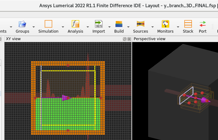
The FDTD file named “y_branch_3D_FINAL.fsp” was automatically generated, but the geometry was not the 3D optimized one as well. It is the same as the one shown in the GDS.
Thus, I would like to also know
Q4. Why the 3D optimized geometry was not shown in y_branch_3D_FINAL.fsp
Q5. Why the 3D optimized geometry was not saved in “y_branch_3D.gds.
Thanks
-
July 22, 2022 at 3:26 pm
Greg Baethge
Ansys EmployeeHi,
Thanks for bringing this to our attention. I could reproduce the issue with the varFDTD optimization. Something is going wrong when generating the polygon from the optimization results. I'm not too sure why, we need to investigate this. I'll keep you posted as quickly as possible.
-
July 22, 2022 at 7:10 pm
mo_911
SubscriberHi Greg,
Thank you for your prompt response. At least I need a GDS file containing a 3D-FDTD optimized geometry as a final output, related to Q5.
-
July 23, 2022 at 12:09 am
mo_911
SubscriberIt would be great if there is a way to export GDS file from the generated file named "adjoint_0.fsp". The optimized geometry is shown in this file after the optimization.
-
August 1, 2022 at 3:37 pm
Greg Baethge
Ansys EmployeeHi,
Apologies for the delay, last week was pretty hectic (I was on a business trip). You can definitely extract the GDS file from the adjoint_0.fsp simulation. The process is the same as the one used in the example (see at the end of the Py script, the variable gds_export_script that is a string containing the commands to export the GDS. You can open the fsp file, then run the commands. Just make sure the script file Lumerical_GDS_auto_export.lsfx is in the same folder.
-
August 2, 2022 at 1:14 am
mo_911
SubscriberHi,
Thank you for your reply in your busy time. Thank you for your advice.
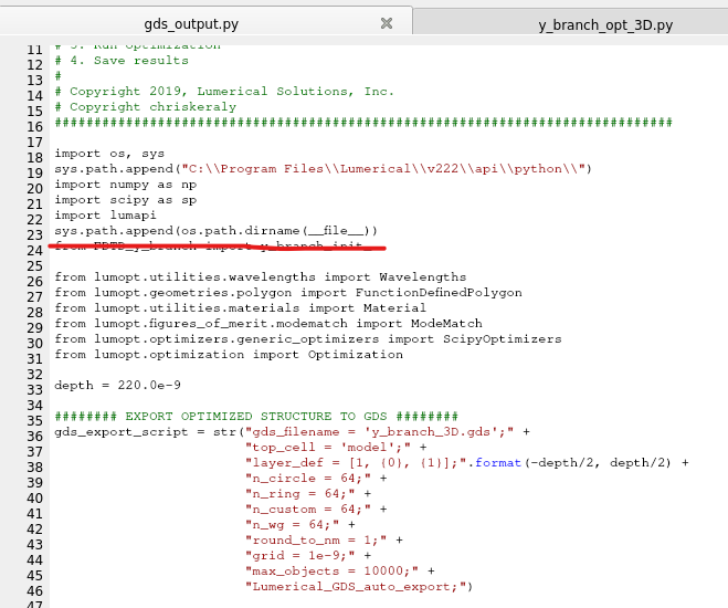
I opened the adjoint_0.fsp simulation file with the optimized geometry shown as polygon, then run the python script with some commands copied from the original python script y_branch_opt_3D.py as shown below. I put Lumerical_GDS_auto_export.lsfx and the python file in the same folder as the adjoint_0.fsp simulation file. However, after running the python script, a GDS file was not generated.
I also tried to use the sample script "gds_contour.lsf" obtained from https://optics.ansys.com/hc/en-us/articles/1500007228522, but it did not work.
-
August 5, 2022 at 12:10 am
mo_911
SubscriberFinally, I was able to export the geometry from “adjoint_0.fsp” for 3D optimization as a GDS file using the method found on the webpage “GDSII Export Automation” (https://optics.ansys.com/hc/en-us/articles/1500006203341) as shown below, by setting the zmin and zmax to -0.11 and 0.11 um, respectively.
Thus, the remained question is
Q2. Why the 2.5D optimized geometry was not used as the initial input for the 3D optimization?
The 3D optimization without the 2.5D optimized geometry still works, but I would like to solve this issue.
-
August 5, 2022 at 3:08 pm
Greg Baethge
Ansys EmployeeGreat to hear you managed to export the gds. We're investigating this problem. For some reason, the cubic interpolation doesn't seem to work when loading results of the optimization although it works during the optimization! I'll keep you posted when I have more information. Thanks for your patience!
-
August 17, 2022 at 11:52 pm
mo_911
SubscriberNow I strongly believe that 2D optimized geometry needs to be used as an initial guess to get the global minimum (or maximum) in 3D optimization. That would be helpful if I can use an object imported from GDS file as an initial guess.
-
August 26, 2022 at 6:58 am
Greg Baethge
Ansys EmployeeThat's typically what we suggest as well: run the 2.5D optimization first as it is much faster, then use its results as the initial guess for the full 3D optimization. This allows to reduce the number of iterations needed to reach the optimized design.
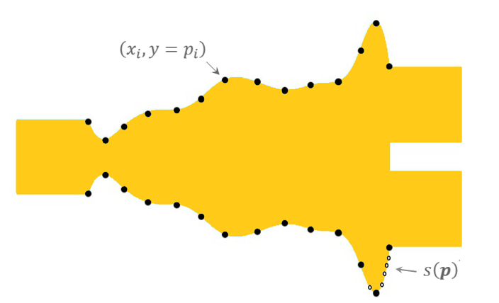
Using the structure imported from a GDS is a bit difficult: for the optimization, the structure is defined with a limited number of parameters (in our example we use 10 parameters):
Then we use an interpolation on a higher number of points to get a smoother shape. The issue we're investigating is related to this interpolation that gives some weird shapes!
Set aside the interpolation issue, to use the GDS, you need to extract from the polygon the y values at x_i to get the initial parameters.
-
August 27, 2022 at 1:26 am
mo_911
SubscriberThank you for your advice. I will try to get the initial parameters from the GDS for 3D optimization.
I hope you can resolve the issue completely soon, but that would be fine if the initial guess for 3D optimization is close enough to the 2D optimized geometry. The initial guess is not necessarily to be exactly the same as the 2D optimized geometry if it is hard to resolve the interpolation issue.
-
September 2, 2022 at 1:17 am
mo_911
SubscriberFor now, I can't use the GDS file as an initial guess for 3D optimization.
I would like to use the 2D optimized geometry or similar geometry as an initial guess for 3D optimization.
-
September 8, 2022 at 2:41 pm
Greg Baethge
Ansys EmployeeApologies for the delay, we're still investigating the issue. You can start the 3D optimizaton using the results (best parameters from the txt file generated at the end of the optimization) from the 2D one. There still might be some issue, but the polygon generation seems to work within the optimization.
-
- The topic ‘Inverse design of y-branch: 2.5D optimized Geometry & GDS were not saved’ is closed to new replies.


-
4999
-
1676
-
1387
-
1248
-
1021

© 2026 Copyright ANSYS, Inc. All rights reserved.

