-
-
August 19, 2024 at 8:52 pm
matt
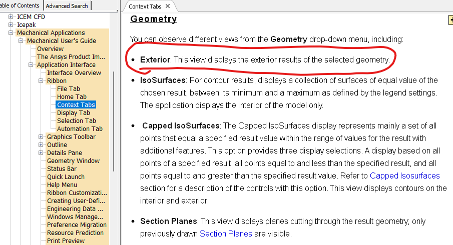
SubscriberWhen displaying stress results in Mechanical, it has been my understanding that the user is only seeing stress results from the outer skin of the model (i.e., internal stresses are ignored). And the Help documentation seems to agree when it says "exterior = displays the exterior results of selected geometry" (first image below). So seemingly, this should behave like APDL with PowerGraphics ON.
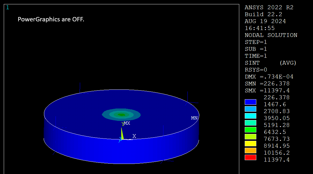
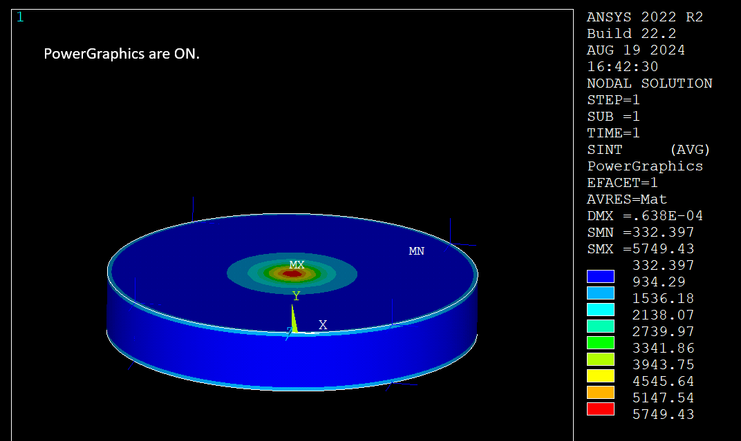
I built a test model to check (images below). It has an internal heat source to create an internal max stress. APDL definitely shows a drastic difference between PowerGraphics ON versus OFF. However, when scoped to bodies, Mechanical definitely does not ignore internal stresses and does behave like PowerGraphics OFF. Can anyone clarify if Mechanical is ignoring internal stress when reporting results?
-
August 20, 2024 at 1:14 pm
Gary Stofan
Ansys EmployeeThere is a detailed explantion of the contour results differences between Mechanical and APDL in the Help file:
Mechanical Application 2024 R2
Mechanical User's Guide
19.3.7. Understanding Averaged and Unaveraged Contour ResultsOverview
Normally, contour results in the Mechanical application are displayed as averaged results. Some results can also display as unaveraged contours. Averaged contours distribute the average elemental nodal results across element and geometric discontinuities. A user option exists that allows you to control whether results are also averaged across body boundaries that contain a conformal mesh. The default setting does not calculate an average across bodies.
Using the Mechanical APDL application terminology, unaveraged contour results display as element nodal contours that vary discontinuously even across element boundaries. These contours are determined by linear interpolation within each element and are unaffected by surrounding elements (that is, no nodal averaging is performed). The discontinuity between contours of adjacent elements is an indication of the gradient across elements.
Results that include the unaveraged contour display option are elemental-nodal quantities such as stress or strain. This option is not available for degree of freedom results such as displacements.
Nodal averaging of element quantities involves direct averaging of values at corner nodes. For higher-order elements, midside node results are then taken as the average of the corner nodes.
In Mechanical, there are two distinct techniques for calculating averaged principal nodal results. The calculation for the first technique is as follows (using stress as the result in question):
Average the component (X, Y, Z, XY, YZ, XZ) stress values from the elements at a common node.
Calculate the principal stresses from the averaged component values
The calculation for the second technique is as follows:
Calculate the principal stress values (from the six component strains) on a per element basis.
Average these values from the elements at a common node.
-
August 20, 2024 at 1:22 pm
matt
SubscriberThank you. My apologies though as I don't think you understood my question. The question basically is asking whether or not internal results are included in the GUI display in Mechanical for a stress result. The Help documentation insinuates that internal results are ignored. But my test model insinuates they are included.
And I used APDL PowerGraphics as a parallel metaphor to explain my question. In other words, PowerGraphics ON excludes internal results, while PowerGraphics OFF includes them.
-
August 20, 2024 at 7:51 pm
Gary Stofan
Ansys EmployeeThe Workbench Mechanical results do not use either GRAPHICS FULL or GRAPHICS POWER because the postprocessing is done in a different way.
Workbench Mechanical uses a technique most similar to Ansys FULL GRAPHICS with nodal averaging and some exceptions.
(The help section I referenced earlier under "Averaging Elemental Nodal Results" has an explanation and graphics that describe Mechanical's nodal averaging method.)
One such exception is that WB Mechanical shows midside node results (like /EFACET 2) whereas ANSYS Full Graphics does not support /EFACET.It seems that when you scope to bodies, you are seeing the effects of this nodal averaging display.
-
August 20, 2024 at 8:03 pm
matt
SubscriberThank you again. I reviewed the Help section you mentioned. The Help section I cited in my initial post insinuates that Mechanical behaves more like GRAPHICS POWER. However, we both agree that it actually behaves more like GRAPHICS FULL. So it seems like that section of Help is not written well since it isn't only displaying exterior results.
-
- You must be logged in to reply to this topic.


-
4708
-
1565
-
1386
-
1242
-
1021

© 2026 Copyright ANSYS, Inc. All rights reserved.


