-
-
June 18, 2020 at 6:25 pm
aaaaa
SubscriberHello
I want to get the contact pressure between gear and shaft which are assembled by shrink fit, but when the mesh number increases, the solution (contact pressure) value also increases.Â
what is the problem where I can not reach the steady solution?
-
June 18, 2020 at 8:59 pm
Bhargava Sista
Ansys EmployeeCould you post a few images of the mesh and the contact settings? As the mesh density increases the contact stiffness increases which in turn may increase the contact pressure too but the % change must reduce as finer mesh is used.
-
June 19, 2020 at 12:29 pm
-
June 19, 2020 at 12:34 pm
-
June 19, 2020 at 1:01 pm
Wenlong
Ansys EmployeeHi,
Looks like the global mesh number is dominated by regions of the gear teeth, and your contact region mesh is still coarse. Can you try adding a mesh size control to the contact faces and only refine the mesh there?
Regards,
Wenlong
Â
-
June 19, 2020 at 9:52 pm
aaaaa
SubscriberHello Wenlong.
Thanks for your attention.
I tried this, but the problem still exists.
The contact pressure increased also. -
June 23, 2020 at 8:46 pm
Bhargava Sista
Ansys EmployeeCan you set the pinball radius to 4e-2 mm? This is just to make sure that the contact algorithm detects the penetration and resolves the penetration properly. I picked a value slightly large than the offset value.
-
June 26, 2020 at 6:35 pm
Wenlong
Ansys EmployeeHi aaaaa,
1) I noticed you defined an offset in the contact geometry modification. Why are you applying that? If you insert a positive offset, you are increasing the initial penetration. You can let your initial geometry determine the penetration amount.Â
2)Â What if your final version of mesh? Your current mesh looks way to coarse as a starting point of the convergence test.
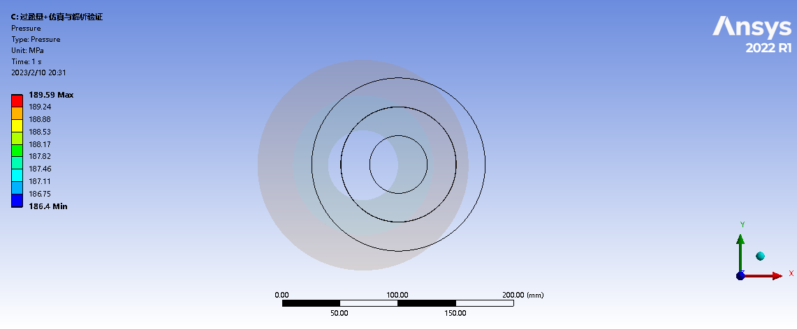
3) When you output contact pressure, look for average value instead of maximum value to check for convergence, as stress concentration is likely to happen.
4) It makes more sense to compare contact pressure vs. the number of elements in contact instead of the total mesh because your other geometry takes the majority of the mesh number. To find the number of contacts, right click "solution information" --> Insert --> Contact.
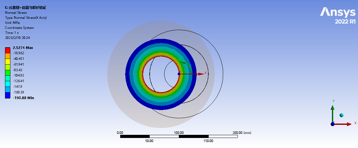
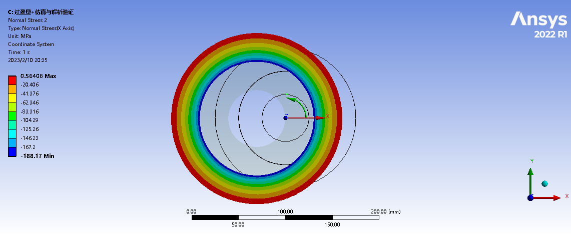
5) Furthermore, if you want to test the model, I suggest you remove the teeth of the gear so it becomes a perfect hollow cylinder, and you can compare with analytical solution.
Please let me know if it helps.Â
FYI, these screenshots are taken from this video:Â https://www.youtube.com/watch?v=O3dHcRnmlNY
Regards,
Wenlong
Â
Â
Â
-
June 27, 2020 at 3:53 pm
Wenlong
Ansys Employee-
February 10, 2023 at 12:48 pm
Ning Xing
SubscriberÂ
Hi Wenlong,Â
When we run an interference fit simulation by using two cylinders, what kind of Support needs to be set?
If any Support is not set, the Interface Pressure and Stress are well matched with analytical results, please see Fig.1, Fig,2 and Fig.3.
The Material of the two cylinders is Structural Steel. The inner and outer radius of the inner Cylinder is 25mm and 50mm. The inner and outer radius of the outer Cylinder is 49.8mm and 75mm. The interference fit is 0.2mm.
However, the Deformation is not right, please see Fig.4.
Thanks for your answering.
Â
Â
-
-
- The topic ‘interference fit’ is closed to new replies.
-
4858
-
1587
-
1386
-
1242
-
1021
© 2026 Copyright ANSYS, Inc. All rights reserved.


