TAGGED: static-structural
-
-
October 18, 2021 at 10:11 am
happykiran
SubscriberHi can anyone explain what kind of interference is used between solid elements (3 DOF) and shell elements (6 DOF)? basically how the DOF is transferred
October 18, 2021 at 10:40 amErKo
Ansys Employee
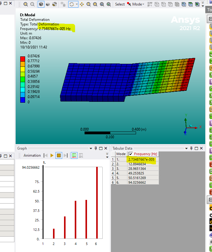
Assuming that the nodes are shared between solid and shell (so using shared topology), then the translational dof are shared, and hence these translations will be transferred - rotations are not transferred across there though, since 3D solid elements do not have rotational dof. To show that, say we connect the two (shared nodes along edge) along an edge, then the shell is hinged about that edge and is allowed to 'hinge/rotate' about the global Z axis as shown below.

Now another way to connect them than just sharing nodes which could lead to the above behaviour is to couple them (solid and shells) via contacts which can be common, see here:
See the help manual for a guide on how to do that:
10.2. Modeling a Shell-Solid Assembly (ansys.com)
Or search for Modelling Shell-Solid Assembly in help.
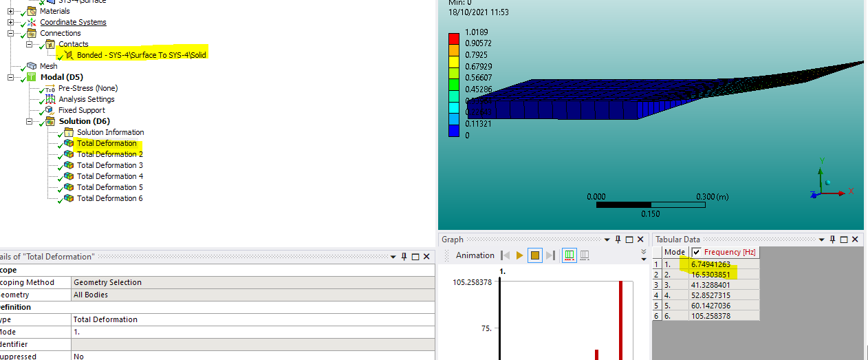
For the above example we do not have the hinge anymore (connected with bonded MPC, the face of the solid to the surface edge):

All the best
Erik
October 27, 2023 at 5:34 pmRyan Royer
Subscriberif i am assembling multiple sheets and multiple solids in one static structural cell model, am i able to create a shared topology between the assembled model? MPC connections are having trouble, so I am wondering if there is a share topology function in mechanical that i can use (i am aware of the DesignModeler and SpaceClaim function)
October 28, 2023 at 1:46 pmpeteroznewman
SubscriberRyan, if the nodes on the shells and solids line up, you can use Mesh Connections to merge coincident nodes so that elements on each side of the boundary will share common nodes. That is similar to what happens when using Shared Topology in DM or SC. However, you must force the mesher to get a matching grid of nodes on coincident faces. Shared topology automatically creates a shared set of nodes on the coincident faces.
Viewing 3 reply threads- The topic ‘Interface between solid and shell elements’ is closed to new replies.
Innovation SpaceTrending discussionsTop Contributors-
5014
-
1681
-
1387
-
1248
-
1021
Top Rated Tags© 2026 Copyright ANSYS, Inc. All rights reserved.
Ansys does not support the usage of unauthorized Ansys software. Please visit www.ansys.com to obtain an official distribution.
-


