-
-
October 17, 2024 at 4:22 pm
suruchi.bala
SubscriberHi,
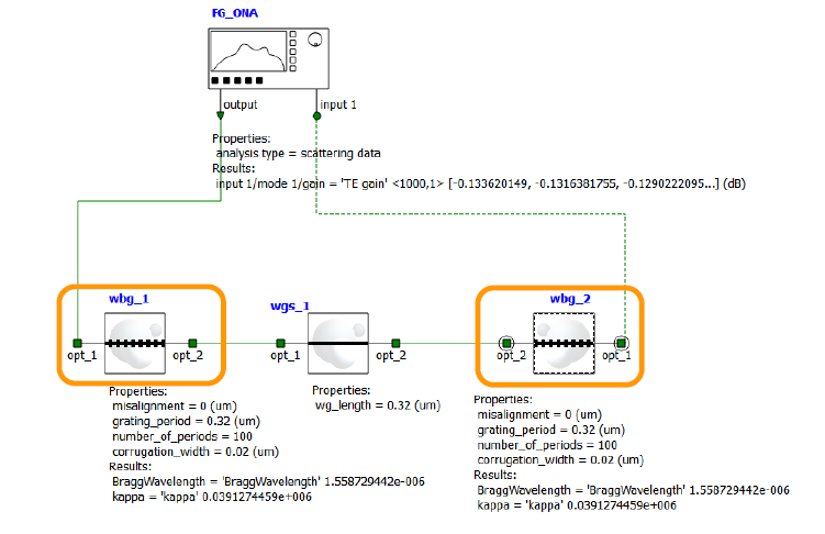
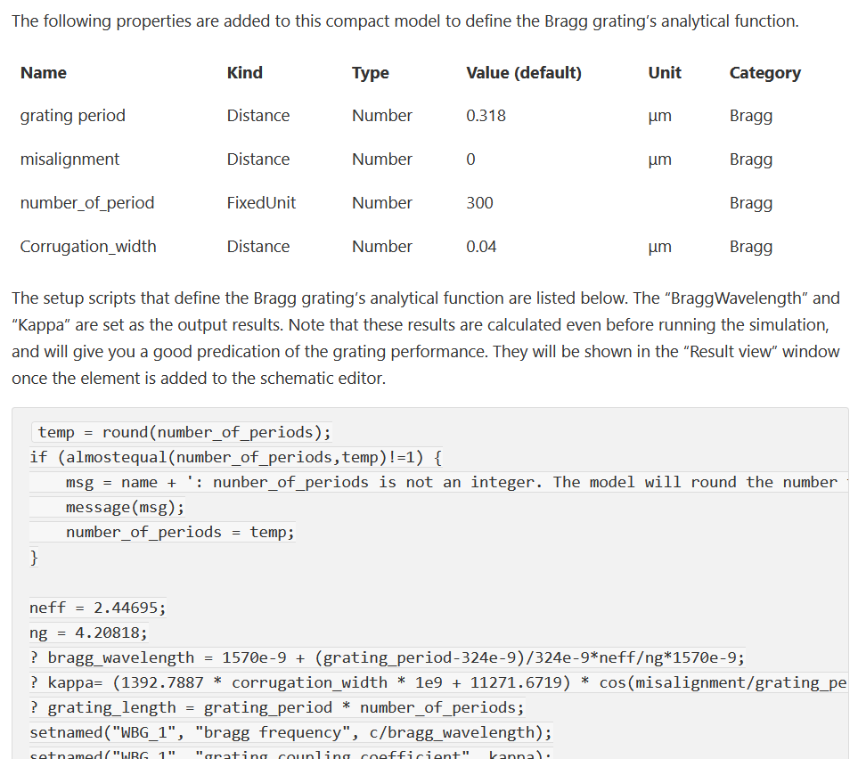
I want to add bragg grating waveguide in Interconnect as shown in the photo (reference image is from one of the lumerical videos). The options available in Interconnect doesn't show any bragg waveguide where period, number of periods etc can be added as shown in the image. How to add such grating waveguide?
-
October 17, 2024 at 10:27 pm
-
October 18, 2024 at 2:49 pm
suruchi.bala
SubscriberHi Guilin,
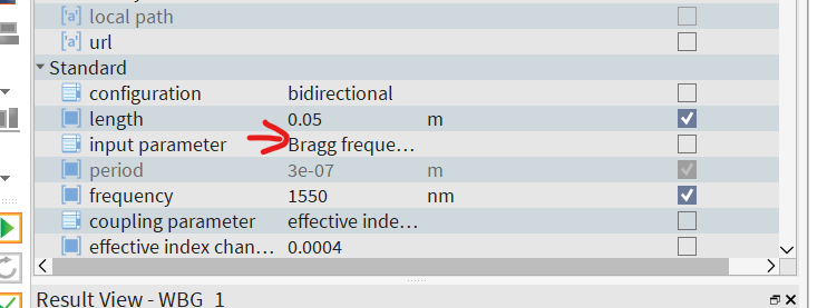
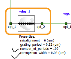
Thank you for your help. I can see grating period but where can I add number of periods and corrugation width?
-
October 18, 2024 at 3:33 pm
Guilin Sun
Ansys EmployeeThis is not physical model, but a math element. So it only needs whatever the specs required. Please check the Bragg graing element articles:
https://optics.ansys.com/hc/en-us/articles/360036108114-Bragg-Grating-WBG-INTERCONNECT-Element
https://optics.ansys.com/hc/en-us/articles/360036108134-Sampled-Bragg-Grating-WBG-INTERCONNECT-Element
-
October 18, 2024 at 3:35 pm
-
October 18, 2024 at 5:46 pm
Guilin Sun
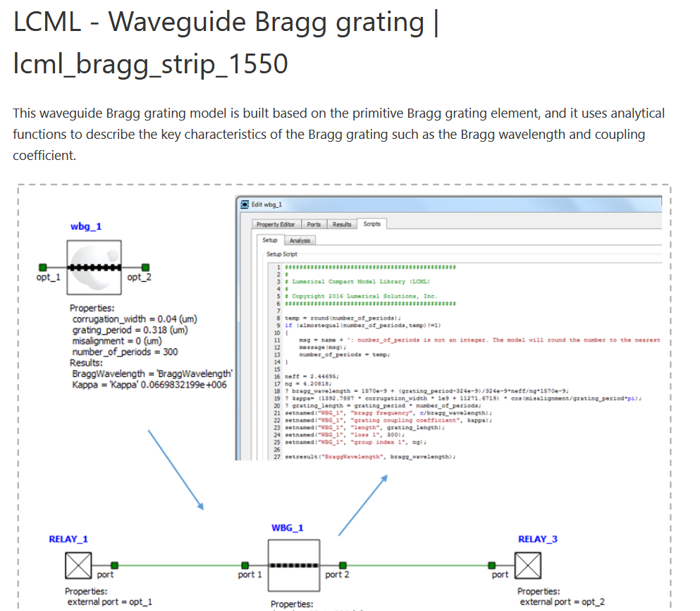
Ansys EmployeeIt is from foundry CML that you need a special permission (license). The CML can have user-defined parameters. It is not in the standard elements. Please contact your account manager for more information.
https://optics.ansys.com/hc/en-us/articles/360037565953-CML-Compiler-product-reference-manual
-
October 20, 2024 at 6:26 pm
suruchi.bala
SubscriberHi Guilin,
I have checked the CML manual but couldn't find the same example. Do you mind sharing the link for the same example.
Thank you.
-
October 21, 2024 at 3:48 pm
-
November 4, 2024 at 6:24 pm
suruchi.bala
SubscriberHi Guilin,
I have a question regarding TE/TM mode in FDTD. I just want to undertstand and confirm, if we use plane wave source injected in xaxis with polarisation angle 0, does this mean its generating TE field?
Regards
Suruchi
-
November 4, 2024 at 6:33 pm
Guilin Sun
Ansys EmployeeThis will depend on your definition of TE mode. There are contradictory definitions about TE/TM. I wrote a post in Chinese https://innovationspace.ansys.com/forum/forums/topic/ansys-insight-youguantetmpianzhenyijimoshiguangyuandewenti/#post-176494 You can goolge translate it. or simply read the following:
https://optics.ansys.com/hc/en-us/articles/360034914633-Finite-Difference-Time-Domain-FDTD-solver-introduction FDTD uses this definition TE: Ex, Ey, Hz
however in the stack example: https://optics.ansys.com/hc/en-us/articles/360034914653-STACK-Optical-Solver-Overview
It is the opposit.
BTW: for new questions please write a new post.
-
- You must be logged in to reply to this topic.


-
4838
-
1587
-
1386
-
1242
-
1021

© 2026 Copyright ANSYS, Inc. All rights reserved.

