TAGGED: ansys-explicit, beam-analysis, explicit-dynamics
-
-
March 6, 2022 at 8:12 am
mhfitri
SubscriberGood day everyone.
I would like to ask for some knowledge share for analyzing a structure in Explicit with beam mesh.
Currently i am trying to observe a reaction of a structure before adding any accessories to hold an impact absorbing of a tubular structure. As Mr @peteroznewman kindly explain before, i could not run without the whole system as all the equipment will be in series and without one of the other, the reaction force will be higher. Thus i am trying for a few months, and keep failing with the solid mesh, as the elements is too high and the simulation time is too long. Thus i am switching for a beam mesh for the tubular structure as it decreases the elements by a lot.
So what am i doing is that i model a small cube with modified density to get the energy required, as i am only observing the elements which get impacted, which having the original density.
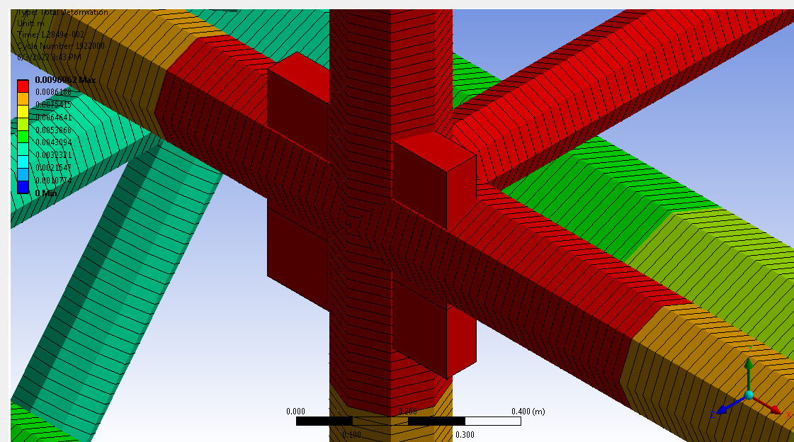
However, for the problem assessment, how do i make sure that cube to hit the beam elements as i could not create any contact from the surface contact to the line elements of the beam. I tried to run the simulations as it, and it seems the model almost went through the beam mesh.
March 6, 2022 at 11:54 ammhfitri
SubscriberOh and the reason i find it might be wrong is that even though there is displacement plot show in the figure above, the stress plots for the beam is 0 Pa which i find it odd even though the beam section results option is turned on
March 6, 2022 at 12:42 pmpeteroznewman
SubscriberANSYS staff are not permitted to download attachments, so are not be able to see your attachment above. Below is the image inserted inline to the discussion.
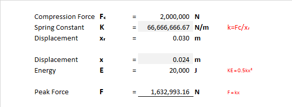
 In your first thread: /forum/discussion/29933/action-reaction-force#latest I described a useful analysis to answer your question. That is a Static Structural analysis. In that analysis, an arbitrary force (say 1000 N) is applied to the face of the rubber pad and the deflection is obtained. Divide the applied force by the static deflection to get the Stiffness, K (N/m). Set the known Kinetic Energy to 1/2*K*x^2 to solve for x, the displacement at which all the Kinetic Energy has been converted to Elastic Strain Energy. Now the peak force for an elastic impact can be calculated from F = K*x.
March 6, 2022 at 5:35 pmmhfitri
SubscriberThank you Sir. I did that, but actually the rubber was just an accessory that i want to add to see the variation of the peak force and the frame has already been built and being used daily. However the peak force gain from the rubber stiffness is too high and already exceed the designed frame input, and if such load is applied, the frame is already broken even before the rubber is attached but currently the frame is still standing upon daily use.
And currently i kind of concern why the model pass though the tubular frame as shown in the figure, is it normal? Also and the stress of the tubular structure meshed by beam elements does not shown in the stress plots.
March 6, 2022 at 7:09 pmpeteroznewman
SubscriberTurn off Thick Shells and Beams and you will find that the rubber pad has not passed through the NODE that defines the location of the beams.
Please share the calculation you did using the method I described and what you found.
March 7, 2022 at 3:17 ammhfitri
SubscriberDear Could you please guide me can i adjust the Thick Shells and Beams option? I am using version r19. I just notice that a small warning says the beam stress/strain will be reported on the Solution Coordinate System. How do i enable this as well?
For the Static simulation to get the stiffness is per below. I applied the displacement to until a value of maximum compression before the rubber starts to tear according to manufacturer. which is the value is how much the rubber needs to be deformed at such deformation.
Showing in figure below the frame is not designed to withstand that much force. By right without the addition of rubber, the force should be higher, but the frame is still good.

March 7, 2022 at 4:36 pmpeteroznewman
SubscriberThe Energy calculation is based on the impact velocity v and the mass of the object m where E = 0.5mv^2
Use that value of E to compute the displacement from the formula 0.5kx^2
Then calculate the Force for that displacement. When you apply that force, what is the stress in the structure?
For a beam, the solution coordinate system is X is axial and Y and Z are orthogonal to the axis.
Read the page in the ANSYS Help system. BEAM188 (ansys.com)
March 8, 2022 at 7:23 ammhfitri
SubscriberDear The E value is subjected as a fix value, which mean, regardless of the mass and the speed, as long if it generated the same amount of energy, the system should be able to handle it. At least that is the earlier design for the frame. The displacement above is calculated from the given fix value of E, thus giving the force by the x.
Thus to view the stress for the beam, i could not simply add the solution but with MAPDL instead? Also why did the stress of the cube having a solid mesh did not shown as well in the stress plot? Although the cube having denser density will not having a accurate stress, i was just curious.
March 8, 2022 at 1:05 pmpeteroznewman
SubscriberThe mass and velocity of the object that will impact an absorbing structure are critically important. The Kinetic Energy of the moving mass is calculated as 0.5mv^2. That energy is converted to elastic energy in the structure. What is the impact velocity? What is the mass of the moving object? Just curious.
March 8, 2022 at 2:03 pmmhfitri
SubscriberThe owner of the frame designed that the frame should be able to hold that much Energy (with the old design team) which is if the impact generated by 1600kg & 5m/s or 625 kg & 8m/s, as long E value is around 20kJ, the frame should be fine.
Viewing 9 reply threads- The topic ‘Interactions Solid to Beam mesh in Explicit Dynamics’ is closed to new replies.
Innovation SpaceTrending discussionsTop Contributors-
4888
-
1587
-
1386
-
1242
-
1021
Top Rated Tags© 2026 Copyright ANSYS, Inc. All rights reserved.
Ansys does not support the usage of unauthorized Ansys software. Please visit www.ansys.com to obtain an official distribution.
-


