TAGGED: 2d-simulation, microLED, stackpurcell-Lumerical-FDTD
-
-
October 18, 2023 at 11:22 am
yd359
SubscriberHi,
I'm doing simulations on light out-coupling efficiencies of planar OLEDs based on the "OLED(2D)" example downloaded from the gallary. Since this is a simple structure, I presume the results from FDTD and STACK should be similar. However, I found the results from the 2D-FDTD model in the "OLED(2D)" are strickly different from those from the STACK based on the same structures and materials.
In specific, according to 2D-FDTD simulation (left), the maximum out-coupling efficiency is ~30% at ~480 nm (also shown in OLED (2D) – Ansys Optics). Using STACK (Customized script), the maximum value is ~15%. From my understanding, the STACK results are most reliable in this planar simple structure. The dramatic differences of the two methods are not likely from the mesh errors in FDTD, and I suspect that there are errors or inappropriate settings in the 2D-FDTD model in "OLED(2D)".
I further performed 3D-FDTD on the same OLED structure and the results are consistent with the STACK results. Therefore, the errors seem to be originated from when incorporating 3D dipoles into the 2D-FDTD simulation.
I would truly appreciate it if you could help me identify the exact issue in the "OLED(2D)" example, and on how to correct the 2D-FDTD simulations on this device.
Yunzhou
-
October 18, 2023 at 6:18 pm
Guilin Sun
Ansys EmployeeAlthough the device seems simple the simulations might not be that intuitive. For example, you need to use exactly the same fitted material, place the dipoles in their correspodent E field components:
Please refer to this example https://optics.ansys.com/hc/en-us/articles/360042161033-Fluorescence-enhancement
There is an example for coparison:
https://optics.ansys.com/hc/en-us/articles/360042713433-FDTD-vs-stackdipole-halfspace-emission-in-a-multilayer-stack
Please also refer this example: https://optics.ansys.com/hc/en-us/articles/360041612594-Purcell-factor-of-a-microdisk
-
October 18, 2023 at 9:53 pm
yd359
SubscriberHi Guilin, thank you so much for your advice and references.
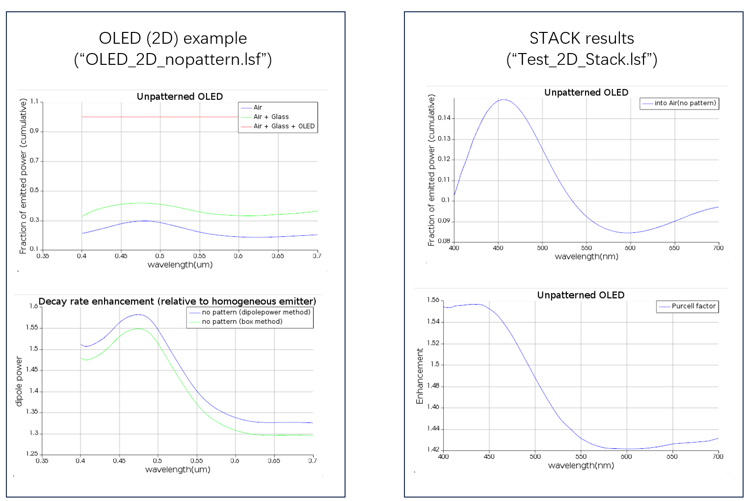
I'm testing the example file from the gallery ("OLED(2D)"), which should be properly settled by default.
Also, when comparing the two methods, I've made sure the materials and thicknesses in FDTD and STACK are exactly the same, which makes the different results puzzling to me.
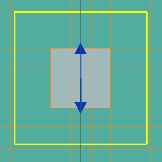
According to the suggestion, I have tried to accurately place the dipole halfway between two mesh points. Unfortunately, the results are barely affected and are still largely deviated from the analytical solves by STACK.
I would also like to note that the two examples you listed are both 3D-FDTD simulations. The problematic example I mentioned in the post is a 2D-FDTD simulation on dipole emission. I've tested that 3D simulations on LEDs are consistent with STACK results. I find it difficult to find 2D simulation examples on dipole radiation.
-
October 18, 2023 at 10:17 pm
Guilin Sun
Ansys EmployeeThis is because 2D is mostly unphysical.
The example I provided has the comparison. Please refer to that example and see if you can improve some settings. Please note that STACK is analytical solution and FDTD is discrete solution. the latter needs careful settings such as mesh accuracy and simulation region, as well as PML.
Please make sure the dipole orientations are the same for STACK and FDTD. 2D simulation will still need 3 dipoles, and different locations as the dipoles must be in the active layer.
Dipole radiation power is very sensitive to locations and relative to the mesh.
-
October 19, 2023 at 8:47 am
yd359
SubscriberThanks, I will have a check on the settings.
-
-
- The topic ‘Inconsistency between 2D-FDTD and STACK on “OLED(2D)” examples’ is closed to new replies.
- Difference between answers in version 2024 and 2017 lumerical mode solution
- Import material .txt file with script
- Absorption cross-section of AuNR excited by prism-based TIR
- How to measure transmission coefficients on a given plane .
- TE Polarization Fraction + Waveguide TE/TM Fraction
- Edge Coupler EME Example Issue
- Lumerical Python API Topology Optimization Error 2025 R1
- 2D inverse design grating coupler
- FDE : Simulation waveguides with electrodes
- Loss of lithium niobate phase modulator
-
2407
-
930
-
599
-
591
-
569
© 2025 Copyright ANSYS, Inc. All rights reserved.