-
-
March 6, 2024 at 6:29 pm
Mert Rıza Yılmaz
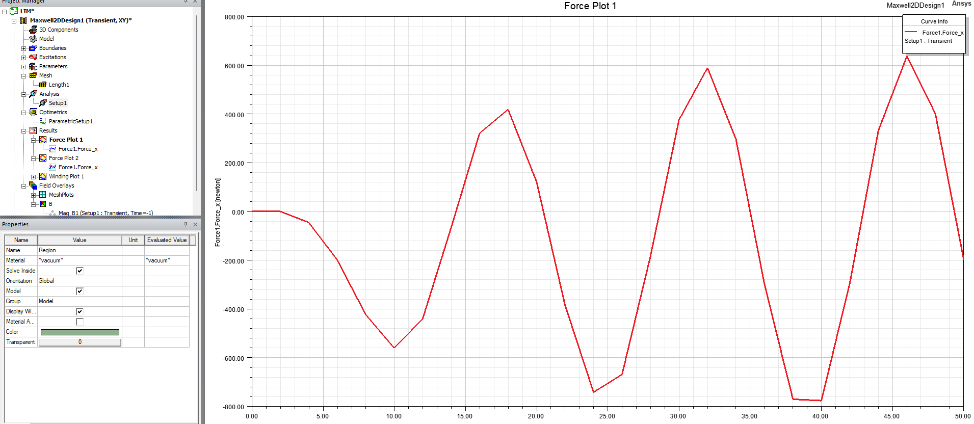
SubscriberAs seen in the image below, the force graph of the linear induction motor is not stable in Ansys Electronics. I followed the suggestions in this link, but it still doesn't work. I don't know what I'm doing wrong. There may be a very simple rule that I need to learn. I tried hundreds of times but it still didn't work. Please help me
-
March 13, 2024 at 5:32 pm
MirandaH
Ansys EmployeeHi, please submit a service request with your model attached, Ansys support engineers will assist. -
March 25, 2024 at 12:29 pm
Mert Rıza Yılmaz
SubscriberThank you for reply. Which e-mail address should I send it to?
-
March 30, 2024 at 12:27 pm
Mert Rıza Yılmaz
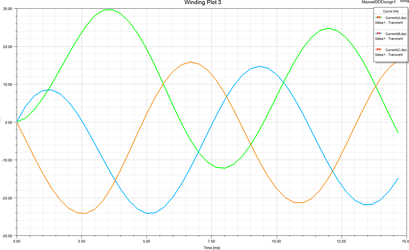
SubscriberI think the problem is that the 3 phase current graph is not smooth. As seen in the image below, there is no waveform as it should be in the 3-phase system, there are increases and decreases. At least the orange and blue phases should be around 24 amps, like the green phase level. I think there are fluctuations in the force graph due to these increases and decreases. Phase A=300*sin(2*pi*60*time), Phase B=300*sin(2*pi*60*time +120deg), Phase C= 300*sin(2*pi*60*time +240deg ). I also tried this like 300*sin(2*pi*60*time + 4*pi/3) phase shift.
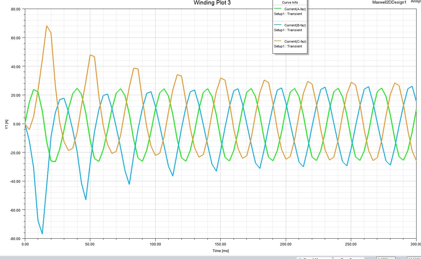
As seen in the image below, it remains stable after some time.
As seen, when the current becomes stable, the force graph also begins to stabilize.
How can I make this more stable? Or how can I make it stable faster? I really can’t figure out where the problem is. I think the problem is in the wave function of the Voltage, but I’m pretty sure the wave function is correct. I really don’t understand what causes the wave function to be so unstable in the first place.
-
March 31, 2024 at 1:49 pm
Mert Rıza Yılmaz
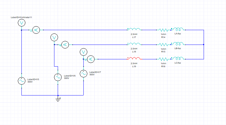
SubscriberI added the circuit, but the force is still not stable. This means that the problem is not in the circuit.
The polarization of the windings of the double-sided linear induction motor is as shown in the image below. Am I making a mistake using this polarization. I tried different polarization types but it didn't work. Or there's instability due to the geometry of the core I use. For instance, is the core's pole pitch too large or the core's neck too short?
-
-
- The topic ‘In Ansys Electronics force graph of the linear induction motor is not stable’ is closed to new replies.


-
4803
-
1582
-
1386
-
1242
-
1021

© 2026 Copyright ANSYS, Inc. All rights reserved.


