-
-
March 23, 2023 at 8:33 am
Lear Ner
SubscriberHi,
quick question:
Say I want to do a structural analysis (deformation/equivalent stress) on a compressor impeller for an overspeed run..
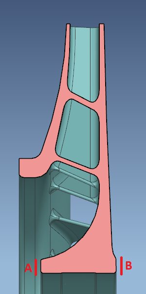
For the overspeed run the impeller bore will have a 0.0mm fit with the shaft. Axial bore face 'B' is pressed against a shaft shoulder. Face 'A' will be limited in axial movement by a plate which is bolted onto the balancing shaft.
Which boundary conditions should I apply in this example?2nd question: Say the impeller bore has an interference/shrink fit with the shaft. Would a simple displacement BC suffice? Where the displacement value is set only to mimic the shrink fit, and leave the other 2 displacement coordinate components at 0 mm?
Thank you
-
March 23, 2023 at 12:59 pm
peteroznewman
SubscriberHi Lear,
For the slip-fit impeller, I suggest scoping a Remote Displacement, Behavior = Deformable, to the two contact faces on the ID of the impeller and setting all six DOF to 0. This completely constrains the rigid body motion of the impeller and allows the solver to run. This allows the ID to expand with the rotational velocity and the distance between the A and B faces to contract due to Poisson’s ratio effects. Make sure that the Behavoir of the Remote Displacement is not set to Rigid because that would prevent the deformations I just described. There is no need to apply any boundary conditions to faces A and B.
An alternative is to model the shaft with a shoulder and the plate. Bond the ID of the plate to the shaft. Slice the face of the shaft at the plate to use Bolt Pretension on the face of the shaft between the plate and shoulder. That will sqeeze the impeller with the force that torquing down a nut on the plate would do. Then apply frictional contact between the A and B faces of the impeller and the shoulder and plate. This requires a two-step solution. Step 1 has a 0 rotational velocity and the bolt pretension builds up. Step 2 the bolt pretension is locked and the rotation velocity is applied.
Answering the second question, I suggest adding a section of the shaft in the hole and putting frictional contact between the shaft and ID of the hole in a 2 step analysis. Step 1 has a zero rotational velocity load, only the interference is resolved, then step 2 applies the non-zero rotational velocity. Make the cut in the shaft at approx. 2 diameters past the A and B faces so you can apply fixed supports to those faces without affecting the material in the interference fit part of the shaft. This type of analysis may benefit from increasing the Displacement tolerance under Analysis Settings, Nonlinear Convergence to a Tolerance of 0.01% instead of 0.5%. Turn on Large Deflection, which should be done for the slip-fit solution also. Assuming the interference is maintained at the overspeed rotational velocity, you won’t need any boundary conditions on faces A and B.
The above correctly apportions the interference between the shaft and impeller according to their respective stiffnesses. There would be a small error if you apply all the interference to the impeller alone.
Regards,
Peter
-
- The topic ‘Impeller boundary conditions’ is closed to new replies.


-
4693
-
1565
-
1386
-
1242
-
1021

© 2025 Copyright ANSYS, Inc. All rights reserved.


