TAGGED: 3d-components, 3d-geomertry, AEDT-ICEPAK, pcb
-
-
October 9, 2023 at 2:46 am
Yin Fang
SubscriberHi there,
I am using the PCB function in automation page try to configure my PCB:
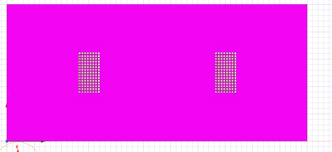
I would like to generate PCB with 2 groups of round vias like this:
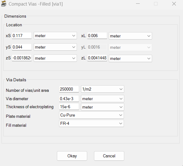
However the module only alow me to drill 1 via for 1 instruction:
The second box "Via Details" seems not working. I can not have multiple vias by setting this, and the plate material is also not displayed for the genrated PCB. The plate is not visible for the created PCB.
I am so confused with it and I can't find anything related to this online. Thank you for anyone's reponse.
Yin Fang
-
October 10, 2023 at 4:51 pm
Iceman
Ansys EmployeeHi Yin,
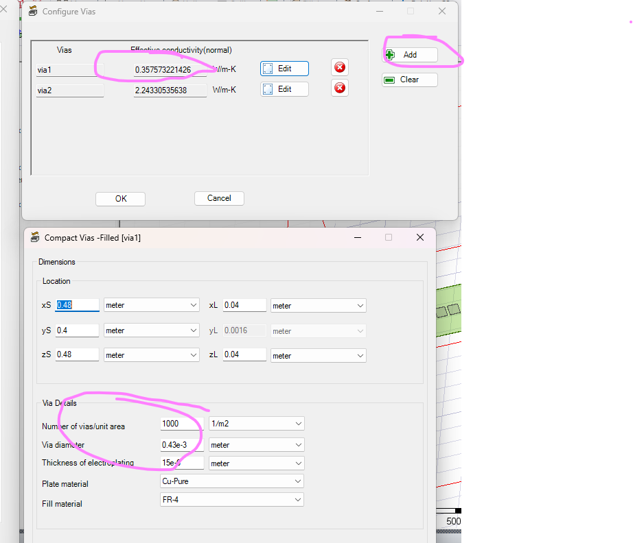
You can use the Add button to add additional vias. The Configure Vias is only available for Compact PCB type. You will only get lumped PCB and Vias with proper material properties. The Via Details will change the effective thermal conductivity. If you want to get the layers of the PCB, you will need to use the Detailed PCB type. Thanks.
-
October 10, 2023 at 5:02 pm
Yin Fang
SubscriberHi there,
Thank you for your reply! Is that means If I have 40 vias I have to get each via individually by the add buttom? I cannot add one group of vias together?
Yin Fang
-
-
October 10, 2023 at 5:08 pm
Iceman
Ansys EmployeeEach Via represents a group of vias together as a lumped solid. There won't be holes created for each individual via. Then material properties will be automattically calculated based on the Via Details setting.
-
October 10, 2023 at 5:26 pm
Yin Fang
SubscriberThank you for your explanation. I think I got it.
Yin Fang
-
-
- The topic ‘Icepak PCB with vias’ is closed to new replies.


-
4708
-
1565
-
1386
-
1242
-
1021

© 2026 Copyright ANSYS, Inc. All rights reserved.


