-
-
July 6, 2018 at 1:25 pm
jamesgr
SubscriberHi everyone,
I am looking to get a mesh of a full centrifugal pump. I have already created the inlet and volute meshes. I just need to now create the mesh of the open impeller and rotating domain. A simplified version of the impeller looks like this.
There exists a clearance between a cutter bar acting as stationary wall and the blade tip of around 1mm. You can see the clearance here.
I wanted to use Tetra to create something quite quickly, as this will eventually need to be automatically meshed during a design optimisation routine, and I thought Tetra would be more robust, but it seems like tets with prisms have a lot of problems with the sharp sweep angle and the clearances.
Does anyone have any suggestions about the best method to mesh this geometry?
I can upload the files if you need them.
Thanks!
James
-
July 9, 2018 at 6:51 am
Naresh Patre
Ansys EmployeeHello,
You need to enable Curvature/Proximity sizing function in Global Mesh setup and specify appropriate Min size and elements in gap based on the gap thickness.
-
July 9, 2018 at 3:35 pm
jamesgr
SubscriberHi nmpatre,
Thank you for taking the time to reply to this post!
I have updated the global mesh set up with the following parameters:
The clearance is 1mm, so the thought process is to have 4 elements in the gap and so the min size limit was set to a quarter of the gap size.
The part mesh set up is as:
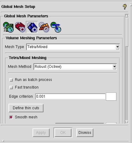
The volume mesh set up has been set as follows:
The edge criterion is set to 0.001 in order to attempt to capture the sharp trailing edge of the blades.
However, I found the Octree method does not seem to be suitable for this geometry as running the cutter took hours. I eventually interrupted it in favour of a bottom up approach.
Using an All Tri, patch independent method, I attempted to begin by creating a surface mesh of the impeller. However, the method seems to have difficulties capturing the sharp trailing edge.
In general, the quality of the surface mesh was quite low (min quality approx 6.9e-7), even though I believe it to be sufficiently refined (if not too refined). I used a Lagrangian smoother, but there was no noticeable difference in quality.
Does anyone have any advice on how I can proceed or guidance of where to look for information?
Regards,
James
-
July 10, 2018 at 6:53 am
Naresh Patre
Ansys EmployeeHello James,
Did you try using ANSYS Meshing application within ANSYS Workbench? If not, I would recommend you to do so since it has many aspects of ICEM CFD meshing technology integrated into it. ANSYS Meshing will help you to overcome the issues that you have reported. Check out below link on ANSYS Meshing basic tutorials.
https://www.youtube.com/playlist?list=PLd23hHm4FCRczS3k0-Sg_yeVSSPnaz4FE
-
July 10, 2018 at 1:40 pm
jamesgr
SubscriberHi again nmpatre,
No, I had not tried Ansys meshing, but I will try it now. Thanks for this and the tutorials!
James
-
July 10, 2018 at 3:05 pm
jamesgr
SubscriberHello again,
I am using Ansys meshing now and it seems to have fixed a number of those earlier issues.
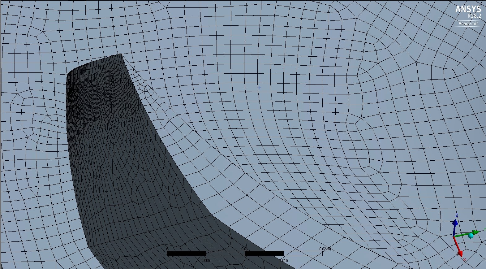
However I am a little trouble with the sharp corner at the trailing edge. Namely due to the sharpness of that corner, I am getting low quality cells in that region.
My question is regarding the feasibility of using an interface right at the top of the blades such that the sharp corner need not be meshed. So the bottom portion acting as the rotating fluid domain would look like this:
With a top portion of thickness corresponding to the desired clearance with an interface between them.
Obviously this would the interface between the regions would not be completely corresponding as there would be missing cut out from the blades in the top portion, but it would mean the sharp corner from the trailing edge need not be meshed. Is this a good approach or even something that Ansys could handle?
Thanks for any advice.
Regards,
James
-
July 11, 2018 at 11:45 am
Naresh Patre
Ansys EmployeeWhat meshing method are you using? Can you try using Tetrahedral - patch conforming meshing method?
-
July 11, 2018 at 12:55 pm
jamesgr
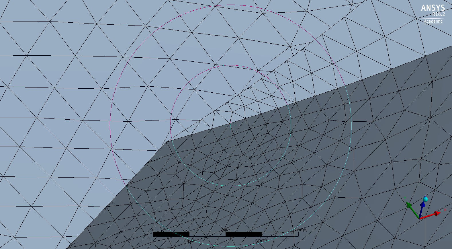
SubscriberI was using the hex dominant with the previous image, but I have also used the Tetrahedral patch conforming method. The below image shows the result.
I worry about the quality of those cells at the very tip of the TE shown here and due to the sharpness of the blade there, there's not much to be done.
Is the previous idea of using another region as the tip clearance region with an interface between this region and the impeller domain not possible then?
James
-
July 11, 2018 at 3:15 pm
jamesgr
SubscriberAs a follow up to the previous question, I have found a paper in which the clearance was modelled as a separate region from the impeller region for a semi axial flow pump http://journals.sagepub.com/doi/pdf/10.1177/1687814017704357
I will see if I can do the same as this would make life a little easier.
Thanks!
James
-
July 11, 2018 at 4:54 pm
jamesgr
SubscriberAs a further update, returning back to ICEM and as a general guide using this forum post.
I was able to create what I hope is a decent enough mesh of the rotating fluid domain for my purposes. I got the attached mesh report for the mesh. I've also attached the mesh file if anyone would like to have a look, but basically using Octree method to create an initial surface mesh, deleting the volume mesh, creating a couple of prisms with prism height limit factor set to one, then splitting these prisms and finally populating the rest of the region with Delauney tets seemed to have done the job for me.
Thanks for your help again nmpatre!
James
-
- The topic ‘ICEM: Meshing rotating domain with open impeller and small vane clearance’ is closed to new replies.


- Element type definition – Ansys Workbench
- CONVERTING STL FILE IN TO SOLID
- Varying ply angle in ACP
- The meshing algorithm cannot find matching topology
- Assiging one parameter as thinkness of few shell objects
- [ANSYS Meshing] how to activate curvature for a sizing in a script?
- Discovery 2024 R2 Crashing
- How to create a mapped mesh in a chain link model with stud.

-
1722
-
624
-
599
-
591
-
366

© 2025 Copyright ANSYS, Inc. All rights reserved.


