-
-
November 25, 2024 at 11:18 am
uzmayaqoob1960
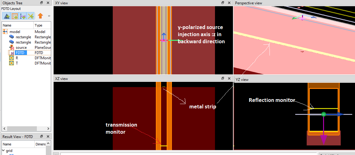
SubscriberHere yellow colored bar is gold bar and substrate is of polyimide(PI) material.I have made all the dimensionsional parameters same as mentioned in the Fig.But i am unable to get the plot like this.Plz let me know where i am lagging?Means operating frequency is 0.69THz.But i am getting very minimal transmission of this unit cell .Plz let me know what to do to reproduce it.I placed a source 10um below the metal bar in substrate and then placed a transmission monitor about 800um above the metal bar .

-
December 4, 2024 at 11:26 pm
anna.wirth-singh
Ansys EmployeeHello,
Thanks for your question. Could you please provide some more information about the effect you wish to model? Are you trying to reproduce a figure from a paper that can be referenced?
It looks like this device may be a microwire polarizer or plasmonic device. In that case, we have a few relevant application gallery examples. If any of these are similar to the device you are trying to model, it may be easiest to start from one of these example files and modify it according to your simulation:
- Microwire polarizer – Ansys Optics
- Polarization-Sensitive Plasmonic Reflectors for HUD – Ansys Optics
- Tunable THz metamaterial based on a periodic array of graphene – Ansys Optics
I can also suggest a few suggestions for troubleshooting. Firstly, it can be very helpful to use a movie monitor to visualize the fields. This can help to identify any obvious errors (for example, if the light is injected in the wrong direction). Since this is a periodic device, I would recommend using Periodic boundary conditions along X and PML conditions along Z. Most likely, the source should be a plane wave, and the option to set the polarization of that wave is in the plane wave source settings. If you wish to inject the light at an angle, then you will need to use Bloch instead of periodic boundary conditions.
I hope this information is helpful. If you are able to share any results from your simulation, that may help with troubleshooting.
Best,
Anna
-
December 5, 2024 at 10:46 am
uzmayaqoob1960
SubscriberDear mam i want to reproduce the above results.I actually want to form gratings of this slit once the transmission response is verfied under normal incidence of x and y-polarized light.Yes mam i ahve applied the same boundary conditions as u suggested but couldn't find the optimal transmission.I am worried about the placement of power monitors and source monitors.Is there any rule of thumb while dealing with plasmonics?
-
December 5, 2024 at 5:29 pm
anna.wirth-singh
Ansys EmployeeA good rule of thumb to follow is that the PML boundaries should be at least lambda/2 away from any structures. Your wavelength of interest is around 400 microns so the transmission monitor 800 microns above the bar (and the PML boundary above that) should be fine. It may be beneficial to place the source a bit further away from the structures, but I do not think this would cause an issue.
Can you please share a screenshot of your simulation setup or the results that you are getting? Is the transmission monitor not returning any results, or is it just returning results that are unexpected? Any information you can provide will help with troubleshooting.
Thanks,
Anna
-
December 6, 2024 at 7:10 am
-
December 11, 2024 at 3:40 pm
anna.wirth-singh
Ansys EmployeeHello,
Thanks for sharing your simulation setup. I don't immediately see any issues with your setup, but it is unusual that both the reflection and transmission would be low - the light should typically leave the simulation through either the T or the R monitor, since the side boundaries are Bloch / Periodic.
Another thing to check would be the simulation time. Would you please check that the simulation is long enough? Resonant structures can trap the light, so the simulation time may need to be increased. To check this, you can add a movie monitor and observe the fields propagating through the system, or you can add a time monitor and view the amplitude of the fields versus time. If you increase the simulation time and the results do not change, then the issue is probably something else.
Best,
Anna
-
- You must be logged in to reply to this topic.


-
4633
-
1535
-
1386
-
1225
-
1021

© 2025 Copyright ANSYS, Inc. All rights reserved.


