-
-
October 10, 2024 at 10:10 am
quoctran0606
SubscriberI am performing hydrodynamic response for laying barge. Two issues need to be investigated.
- Currently, I am done with the hydrodynamic response with the laying barge without superstructure. I tried to model the superstructure into a model but it got the error "Illegal connection". I believe that it came from the connection bwt the surfaces of the superstructure. My purpose in modeling superstructure is to calculate the wind force.
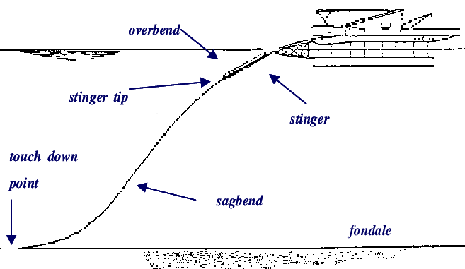
- I assume that the rigid pipeline of laying barge acting line mooring line with tension. The tensioner on the Laying Barge and roller on the stinger are supporting structures for rigid pipelines to get the right configuration. I am going to model it like mooring line but I don't know how to define the contact btw a mooring line to roller on the stinger. Furthermore, is there any alternative way to define exactly rigid pipeline in this case?

-
October 15, 2024 at 12:51 pm
Shuangxing Du
Ansys Employee(1) It is not necessary to define the super structure for wind drag calculation by Aqwa. Instead, please define the wind drag force/moment coefficients for all the possible directions from -180 degree to 180 degree. If you really want to define the external surfaces of supper structure, it is OK, but please remove all the internal surfaces, especially between the upper deck and supper structures.
(2) If you want model the rigid pipeline by a mooring line, the boundary condition between mooring and laying barge/roller on the stinger cannot be modelled properly by Aqwa, as the ball/socket joint condition is applied at the fairlead point of the cable in Aqwa.
(3) Not sure what you mean "the rigid pipeline". If it is rigid, you can define it by a structure with multiple tube elements. Then the supporting/constraining conditions between this "structure" and the laying barge/roller on the stinger can be defined by series of fenders.
-
October 16, 2024 at 4:24 am
quoctran0606
SubscriberThank you for your detailed response.
(2). The barge is laying the steel pipe with constant tension by tensioner and stinger supporting. My assumption to model it like mooring line and adjust mooring length to maintain the initial tension as mentioned tension. My purpose to know how the mooring system behaviour.
(3) The steel pipe + concrete coated during laying will be have its configuration under stinger supporting. As your response, that steel pipe will be modeled with multiple tube element and stinger supporting acting like series of fender. So I afraid that the pipe will be not got the right configuration (overbend region on stinger supporting, sagbend region and touch down point of pipe)

-
October 30, 2024 at 3:58 am
quoctran0606
SubscriberCould I have your advise on it, sir?
-
October 30, 2024 at 9:11 am
Shuangxing Du
Ansys EmployeeModelling steel pipe by Aqwa mooring line may not be suitable. As mentioned previously, the pipe boundary condition at the stinger tip cannot be defined properly, as the bounday condition of Aqwa mooring line at the fairlead is of ball/socket type.
-
- You must be logged in to reply to this topic.


-
4838
-
1587
-
1386
-
1242
-
1021

© 2026 Copyright ANSYS, Inc. All rights reserved.


