

-
-
October 22, 2020 at 9:47 am
hariprakash
SubscriberHi everyone,
I am currently trying to model a single flexible robot arm. The arm deforms as pressure is being applied but even if more pressure is applied, the bending is the same. Below attach are my settings as well as my geometry as well as the end product I want to achieve.
October 23, 2020 at 2:11 ampeteroznewman
SubscribernYou included a zip file with the image of the Final Result.n But you have a structure that doesn't have these side pockets that create the structure.n
 How do you expect to get the final result when the geometry doesn't have the features needed to create the final result?n
October 23, 2020 at 3:30 pmSubscriberI am sorry for including the wrong image. The post is updated with a new photo. What am trying to achieve is to bend my arm the way the image is shown. For now its bending but even if I increase the pressure, its not bending morenOctober 24, 2020 at 11:26 amSubscriberYou can't update the post with a new photo. In this new Forum, you can only edit for 1 hour, then the post is frozen. Attach the new photos in a new comment below.nOctober 24, 2020 at 4:03 pmSubscriber
How do you expect to get the final result when the geometry doesn't have the features needed to create the final result?n
October 23, 2020 at 3:30 pmSubscriberI am sorry for including the wrong image. The post is updated with a new photo. What am trying to achieve is to bend my arm the way the image is shown. For now its bending but even if I increase the pressure, its not bending morenOctober 24, 2020 at 11:26 amSubscriberYou can't update the post with a new photo. In this new Forum, you can only edit for 1 hour, then the post is frozen. Attach the new photos in a new comment below.nOctober 24, 2020 at 4:03 pmSubscriber here is the photo as requested. The problem i'm facing is that is bending the directing im applying pressure to. But the angle of curvature remains the same even more pressure is applied.n
October 27, 2020 at 12:33 amSubscribernThe cross-section geometry doesn't look like the photo. Next time you take a photo, try using a dark background. White on white is not easy to see.nNovember 1, 2020 at 8:45 amSubscribernI am sorry for the late reply Peter. I redid my simulation and almost got my answer but I would like to know if I can bridge pressure and joint rotation together. Below are the settings ive made. Properties i am using arenDensity - 1190kg/m^3nHyperelastic - Yeoh modelna. Contactsn
here is the photo as requested. The problem i'm facing is that is bending the directing im applying pressure to. But the angle of curvature remains the same even more pressure is applied.n
October 27, 2020 at 12:33 amSubscribernThe cross-section geometry doesn't look like the photo. Next time you take a photo, try using a dark background. White on white is not easy to see.nNovember 1, 2020 at 8:45 amSubscribernI am sorry for the late reply Peter. I redid my simulation and almost got my answer but I would like to know if I can bridge pressure and joint rotation together. Below are the settings ive made. Properties i am using arenDensity - 1190kg/m^3nHyperelastic - Yeoh modelna. Contactsn b. Jointsn
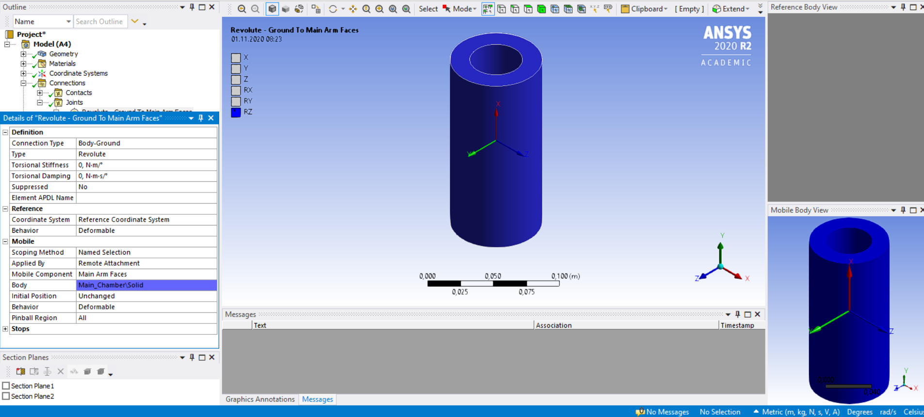 c. Pressuren
 d. Joint rotationn
 e. Analysis settingsn
 f. Result 1n
 g. Result 2n
 nAs you can see there are 3 chambers within the main chamber. My goal is to inflate one of the internal chamber with pressure and where size of inflation should be proportional to the amount of pressure fed and the arm should bend accordingly. As you can see from Result 1, there is bending but no inflation but when I suppress Joint in analysis settings, I get my inflation as in Result 2. How do i combine both where the bending is affected by the pressure applied in of the internal chambers.nnThank you in advance. n
November 1, 2020 at 1:33 pmSubscribernThe images you showed in your first post didn't disclose that you were using joints. Your model is supposed to simulate what you have in the real world. There is no joint in the real world. Delete the joints from your model.nI understand the goal is more pressure induces more bending. That is easily done with a different geometry shape such as this:n
nAs you can see there are 3 chambers within the main chamber. My goal is to inflate one of the internal chamber with pressure and where size of inflation should be proportional to the amount of pressure fed and the arm should bend accordingly. As you can see from Result 1, there is bending but no inflation but when I suppress Joint in analysis settings, I get my inflation as in Result 2. How do i combine both where the bending is affected by the pressure applied in of the internal chambers.nnThank you in advance. n
November 1, 2020 at 1:33 pmSubscribernThe images you showed in your first post didn't disclose that you were using joints. Your model is supposed to simulate what you have in the real world. There is no joint in the real world. Delete the joints from your model.nI understand the goal is more pressure induces more bending. That is easily done with a different geometry shape such as this:n You have photographs of something that is bending, but the photo does not look like the geometry. I have circled what looks like a square cross-section, but your geometry shows a circle. I don't believe your geometry matches the physical prototype. Better photographs might convince me that you have accurate geometry in your model. Maybe you can take an X-ray or CT scan of your device and see what shape is on the inside.n
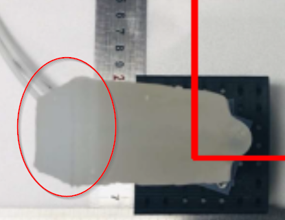 n
November 1, 2020 at 3:01 pmSubscriberThank you Peter. I understand now. Guess ill check the real model and then try out. nNovember 9, 2020 at 6:40 pmSubscriberHi Peter ,nHope you are doing well. I am doing another new geometry using hyper elastic material. Single chamber, 2 chambers and 3 chambers. The bending of the 1 and 2 chambers are what i expected but for the 3 chambers, the model isnt solving. I just added extra one chamber for the 2 chamber model. The settings are the same just but still i couldnt get ANSYS to solve. As you can see, the bending isnt what im getting from 3 chambers. After all, i just added one more chamber from the 2 chamber modeln1 chambern
n
November 1, 2020 at 3:01 pmSubscriberThank you Peter. I understand now. Guess ill check the real model and then try out. nNovember 9, 2020 at 6:40 pmSubscriberHi Peter ,nHope you are doing well. I am doing another new geometry using hyper elastic material. Single chamber, 2 chambers and 3 chambers. The bending of the 1 and 2 chambers are what i expected but for the 3 chambers, the model isnt solving. I just added extra one chamber for the 2 chamber model. The settings are the same just but still i couldnt get ANSYS to solve. As you can see, the bending isnt what im getting from 3 chambers. After all, i just added one more chamber from the 2 chamber modeln1 chambern 2 chambersn
 n3 chambersn
 nnThank you in advance Peter. n
November 10, 2020 at 5:03 pmSubscriberhi Array nHope you are doing well. i tried again but still fail to solve in ANSYS.nBelow are the images.n
nnThank you in advance Peter. n
November 10, 2020 at 5:03 pmSubscriberhi Array nHope you are doing well. i tried again but still fail to solve in ANSYS.nBelow are the images.n The difference between the two images are that the first one has no pressure in the last chamber (Chamber 3) and the second image has pressure in the last chamber (chamber 3). When there is no pressure, ANSYS able to solve it but when i include pressure in the 3rd chamber, ANSYS couldn't solve it. The error displayed was.nThe solver engine was unable to converge on a solution for the nonlinear problem as constrainednThe ANSYS i am using is ANSYS 2020R2 student version.nnThank you in advance Array .I really appreciate your helpnnHari Prakash Thanabalann
November 10, 2020 at 5:39 pmSubscriberArraynA Google search of unable to converge on this site has 192 results. nPlease read them and try some of the most common suggestions.nhttps://www.google.com/search?q=site%3Aforum.ansys.com+%22unable+to+converge%22&oq=site%3Aforum.ansys.com+%22unable+to+converge%22&aqs=chrome..69i57j69i58.11142j0j7&sourceid=chrome&ie=UTF-8nNovember 11, 2020 at 12:22 pmSubscribernis it possible to get the bending angle in ansys for my structure?.Thank you in advancenNovember 12, 2020 at 12:51 amSubscribernLook into the Flexible Rotation Probe. /forum/discussion/1163/measuring-rotation-in-ansys-mechanical-application-workbenchnNovember 12, 2020 at 1:17 pmSubscribernHi Peter. Hope you are fine. I am having a slight problem with my data. n
The difference between the two images are that the first one has no pressure in the last chamber (Chamber 3) and the second image has pressure in the last chamber (chamber 3). When there is no pressure, ANSYS able to solve it but when i include pressure in the 3rd chamber, ANSYS couldn't solve it. The error displayed was.nThe solver engine was unable to converge on a solution for the nonlinear problem as constrainednThe ANSYS i am using is ANSYS 2020R2 student version.nnThank you in advance Array .I really appreciate your helpnnHari Prakash Thanabalann
November 10, 2020 at 5:39 pmSubscriberArraynA Google search of unable to converge on this site has 192 results. nPlease read them and try some of the most common suggestions.nhttps://www.google.com/search?q=site%3Aforum.ansys.com+%22unable+to+converge%22&oq=site%3Aforum.ansys.com+%22unable+to+converge%22&aqs=chrome..69i57j69i58.11142j0j7&sourceid=chrome&ie=UTF-8nNovember 11, 2020 at 12:22 pmSubscribernis it possible to get the bending angle in ansys for my structure?.Thank you in advancenNovember 12, 2020 at 12:51 amSubscribernLook into the Flexible Rotation Probe. /forum/discussion/1163/measuring-rotation-in-ansys-mechanical-application-workbenchnNovember 12, 2020 at 1:17 pmSubscribernHi Peter. Hope you are fine. I am having a slight problem with my data. n


 Im just wondering, why is the position of my node in either X, Y or Z axis is extremely small. it starts with like e-06 m. How do i start my point from 0 and then displays the coordinates from there.Thank you Petern
November 12, 2020 at 5:04 pmSubscribernIf you want control over the labels on the axis, for example a zero label instead of 1e-6, then copy the Tabular Data out of Mechanical and paste into Excel where you have that kind of control.nNovember 12, 2020 at 5:48 pmSubscriberThank you nNovember 13, 2020 at 6:48 pmSubscribernHope you're doing ok. Just want to ask you. What is the min, max and average column in total deformation? where can detailed information about it?.Thank you in advancenNovember 14, 2020 at 2:09 amSubscriberWhen you pick a vertex, they are all equal.nWhen you pick an edge/curve, face/surface or body, then it computes those statistics for all the nodes on the scoped geometry.nNovember 14, 2020 at 9:00 amSubscriberThank you nNovember 15, 2020 at 10:27 amSubscribernHope you are alright. Just wanna ask. How do i specify a node on a specific location? For example, my cylinder height is .065m. Now i wanna specify a node at the top of the cylinder at (0, .065, 0). That way, i can get the mid point at the end effector of my robot.Thank you in advance peter.nNovember 15, 2020 at 10:00 pmSubscribernI tried the flexible rotation probe you mentioned by i am getting like 0 degrees as the answer. Im sure im missing something but couldnt figure out what is it.n
Im just wondering, why is the position of my node in either X, Y or Z axis is extremely small. it starts with like e-06 m. How do i start my point from 0 and then displays the coordinates from there.Thank you Petern
November 12, 2020 at 5:04 pmSubscribernIf you want control over the labels on the axis, for example a zero label instead of 1e-6, then copy the Tabular Data out of Mechanical and paste into Excel where you have that kind of control.nNovember 12, 2020 at 5:48 pmSubscriberThank you nNovember 13, 2020 at 6:48 pmSubscribernHope you're doing ok. Just want to ask you. What is the min, max and average column in total deformation? where can detailed information about it?.Thank you in advancenNovember 14, 2020 at 2:09 amSubscriberWhen you pick a vertex, they are all equal.nWhen you pick an edge/curve, face/surface or body, then it computes those statistics for all the nodes on the scoped geometry.nNovember 14, 2020 at 9:00 amSubscriberThank you nNovember 15, 2020 at 10:27 amSubscribernHope you are alright. Just wanna ask. How do i specify a node on a specific location? For example, my cylinder height is .065m. Now i wanna specify a node at the top of the cylinder at (0, .065, 0). That way, i can get the mid point at the end effector of my robot.Thank you in advance peter.nNovember 15, 2020 at 10:00 pmSubscribernI tried the flexible rotation probe you mentioned by i am getting like 0 degrees as the answer. Im sure im missing something but couldnt figure out what is it.n Thank you in advance petern
November 15, 2020 at 10:18 pmSubscribernWhat angle is reported when you set the Result Selection to the Z axis. That is the axis about which the deformation angle would be largest. It looks like rotation about the Y axis should be close to zero.nNovember 16, 2020 at 8:09 amSubscriberGood morning Peter nHope you are doing alright.n
Thank you in advance petern
November 15, 2020 at 10:18 pmSubscribernWhat angle is reported when you set the Result Selection to the Z axis. That is the axis about which the deformation angle would be largest. It looks like rotation about the Y axis should be close to zero.nNovember 16, 2020 at 8:09 amSubscriberGood morning Peter nHope you are doing alright.n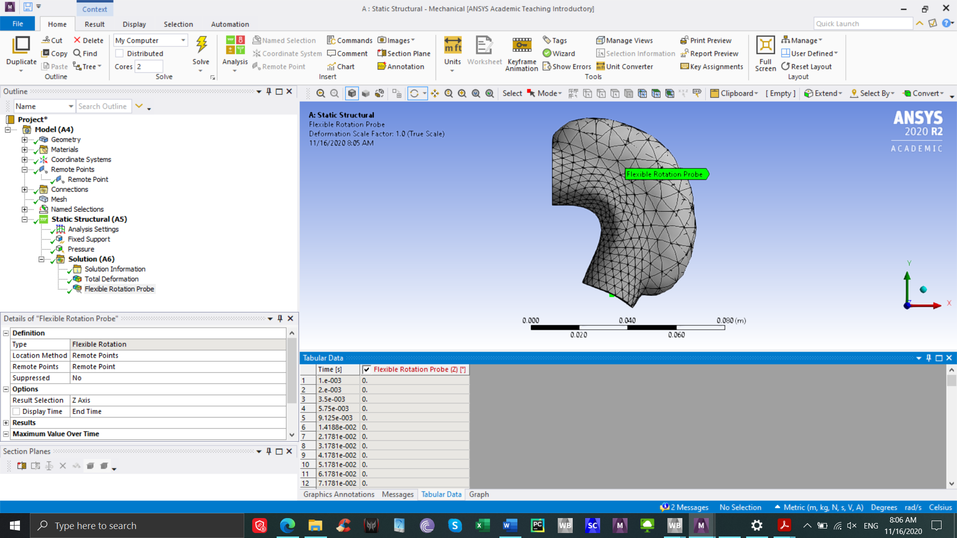 As you can see on the above image, the angle for the Z axis is also 0. This is what i did. nCreated a remote point on the tip of the end effector at (.065, 0, 0)nApply Flexible rotation probe using the remote point. nAm i missing a step, ?.Thank you in advance, Petern
November 16, 2020 at 10:49 amSubscribernI redo my simulation but this time i used the command (Measure_Pilot=_npilot). I got the bending angle. I wanna thank you for it. But there is a thing i wanna clarify with you. nThis is the bending angle for the end effector (face) (max=116 degrees)n
As you can see on the above image, the angle for the Z axis is also 0. This is what i did. nCreated a remote point on the tip of the end effector at (.065, 0, 0)nApply Flexible rotation probe using the remote point. nAm i missing a step, ?.Thank you in advance, Petern
November 16, 2020 at 10:49 amSubscribernI redo my simulation but this time i used the command (Measure_Pilot=_npilot). I got the bending angle. I wanna thank you for it. But there is a thing i wanna clarify with you. nThis is the bending angle for the end effector (face) (max=116 degrees)n This is the bending angle for the 2 faces (body and end effector) (max=67.8 degrees)n
 I just wanna know, why there is a difference between them?.Thank you in advance Petern
November 17, 2020 at 12:55 amSubscriberThe flexible rotation probe creates a pilot dependent node that follows the average motion of all the independent nodes. That means it adds no stiffness to the structure.nThe proper way to use it is to select all the nodes on an end face. nThe first time you tried it, you only picked a single node on a solid element, and a single node on a solid element has no rotational DOF so the angle output is always zero.nYou can pick several faces, but then you are averaging the rotation of all those faces and the faces that don't rotate much will pull down the average from the faces that rotate a lot.nNovember 17, 2020 at 9:40 amSubscriberGood morning Peter nThank you so much for you explanation and your help all this while. I really appreciate it. You have yourself a great day.nnHarinViewing 26 reply threads
I just wanna know, why there is a difference between them?.Thank you in advance Petern
November 17, 2020 at 12:55 amSubscriberThe flexible rotation probe creates a pilot dependent node that follows the average motion of all the independent nodes. That means it adds no stiffness to the structure.nThe proper way to use it is to select all the nodes on an end face. nThe first time you tried it, you only picked a single node on a solid element, and a single node on a solid element has no rotational DOF so the angle output is always zero.nYou can pick several faces, but then you are averaging the rotation of all those faces and the faces that don't rotate much will pull down the average from the faces that rotate a lot.nNovember 17, 2020 at 9:40 amSubscriberGood morning Peter nThank you so much for you explanation and your help all this while. I really appreciate it. You have yourself a great day.nnHarinViewing 26 reply threads- The topic ‘Hyperelastic Material Not Deforming Much’ is closed to new replies.
Innovation Space Trending discussions
 Top Contributors
-
peteroznewman
 5694
5694 -
scabo
 1891
1891 -
Dennis Chen
 1419
1419 -
javat33489
 1305
1305 -
Shyam Prasad V Atri
1021
Top Rated Tags
© 2026 Copyright ANSYS, Inc. All rights reserved.
Ansys does not support the usage of unauthorized Ansys software. Please visit www.ansys.com to obtain an official distribution.
-


The Ansys Learning Forum is a public forum. You are prohibited from providing (i) information that is confidential to You, your employer, or any third party, (ii) Personal Data or individually identifiable health information, (iii) any information that is U.S. Government Classified, Controlled Unclassified Information, International Traffic in Arms Regulators (ITAR) or Export Administration Regulators (EAR) controlled or otherwise have been determined by the United States Government or by a foreign government to require protection against unauthorized disclosure for reasons of national security, or (iv) topics or information restricted by the People's Republic of China data protection and privacy laws.
