-
-
January 11, 2022 at 7:34 pm
Rameez_ul_Haq
SubscriberConsider a rectangular cross sectional solid beam, fixed at one end and a uniform shear force applied to the other end.
Below shows the side view for this beam.
January 12, 2022 at 12:58 pmRameez_ul_Haq
Subscriber,would be extremely pleased to hear your take on this one, sir.
January 12, 2022 at 1:10 pmpeteroznewman
SubscriberThe neutral axis isn't a useful concept when the whole cross-section isn't carrying the load.
You should plot the internal forces passing through a cross-section of interest.
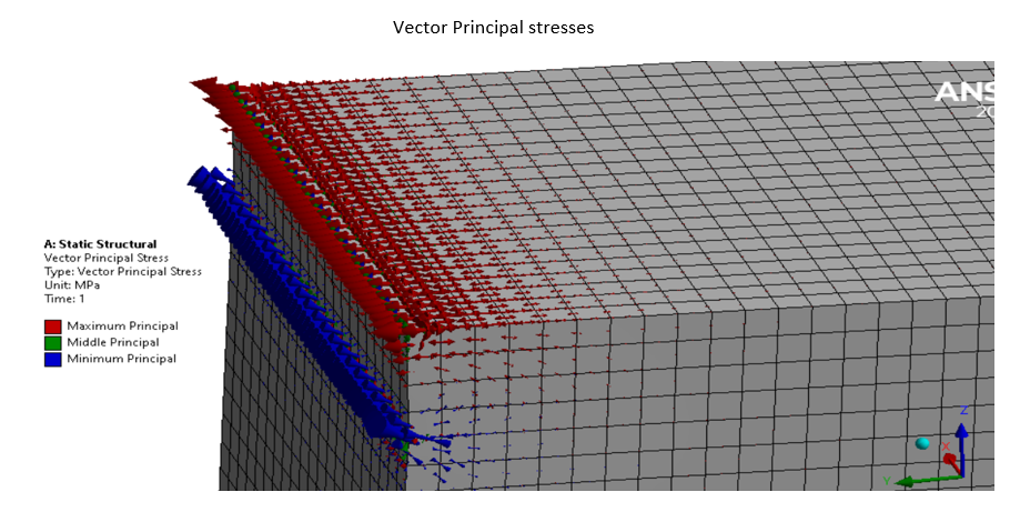
You should make a Principal Stress Vector plot.
January 12, 2022 at 7:45 pmRameez_ul_Haq
Subscriber,so does it mean we cannot calculate the maximum stresses by using the concept of neutral axis through analytics, for the example I have mentioned? And only FEA is the only solution?
But lets do using FEA. Below shows a model I was talking about.


 The actual reason why I asked this question is to understand that how would the forces near the support be distributed? I mean should the half of support be experiencing tension and half experiencing compression? Or all of it experiencing tension (because the support is above the neutral axis)? How can I make use of Vector principal plot and Force reaction plot for my interpretation?
January 12, 2022 at 8:33 pmRameez_ul_Haq
Subscriberthe primary purpose for me of opening this thread here was to basically understand the difference between the reaction moment (arising from a static equilibrium model) and a moment arising from a moment arm in a Rigid Body motion.
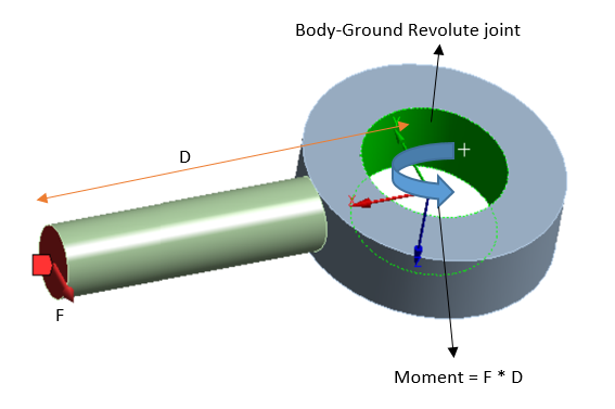
Please observe the model below, showing a Rigid Body motion about the Z axis of revolute joint.
 How is this moment different from the reaction moment that we see on the fixed support of a cantilever beam (subjected to shear force on the other end) in a static equilibrium model? Both models have a shear force at one end and a distance D, and when F is multiplied by D, it gives the same moment (rather it be reaction moment or moment arising from moment arm). So what would be the difference between these two moments.
January 13, 2022 at 12:28 ampeteroznewman
SubscriberThe Neutral Axis (or plane) is only useful for geometry that can be reduced to a beam or shell. This solid model with a thin strip at the top violates the assumptions that makes a Neutral Axis useful.
For the block supported only by a thin strip at the top of the fixed end, you can see in the Vector Principal Stress plot that there is compression (blue arrows) along the bottom of the strip and tension (red arrows) along the top of the strip. Use a vertical plane to cut the body at the midplane, it will be easier to see the Vector Principal Stress along the whole part since it drops to zero at the side faces. Or you could do a 2D Plane Strain model and the surface you mesh is always inside the material.
I will post this comment to your first reply. I will post another comment for your second reply at a later date.
January 13, 2022 at 7:10 amRameez_ul_Haq
Subscriber,okay so it means that the moment will ultimately be transferred in terms of tension and compression, no matter how small or big the supported face is (if there is only external shear force acting on the other end). Understood.
Sure sir. Eagerly waiting for your reply :)
January 13, 2022 at 1:15 pmpeteroznewman
SubscriberFor the revolute joint, is there a Joint Load of type Moment applied to balance F*D? That would generate a zero pivot error in a Static Structural model unless you used Inertia Relief.
If the joint load was a Rotation of 0 degrees, then you could probe the reaction moment on the joint. That would solve without the zero pivot error.
In either case, the nodes around the cylindrical face get the same force vectors, which are mostly tangential in direction.
The cantilever flat face has force vectors on the nodes are mostly horizontal in direction.
January 13, 2022 at 1:55 pmRameez_ul_Haq
Subscriber,sir actually the thing is that in the second example I posted here of body-ground revolute joint, I don't wanna have any static equilibrium. I want that model to actually rotate with a moment = F *D. What I was seeking for is how is this moment (coming from the second example of Rigid Body motion) different from the previous example (reaction moment at the small support)? Since both have the same value of F* D. Now, one can argue that the second Rigid Body motion example doesn't resist the moment of F * D but the first static equilibrium example resists this moment of F* D. Then my question becomes should I (and if I can, then how) use this moment arising from moment arm in Rigid Body motion to size my structure? Can my structure plastically fail or fracture in Rigid Body motion (like in the second example I have shown) and if yes, then how does this moment (which is not being resisted) have an effect on it?
For a static equilibrium case, we use simple equations to size the structure (to reduce weight); like using flexural formula to find the max bending stresses, using shear formula to find the max shear stress, then iterating the cross sectional parameters until the max von-mises stress becomes equal to the yield strength (or a factor of it). In these equations, I make use of the max moment. But for the sizing of structure which is only undergoing a Rigid Body motion, I don't know how to do it. Should I also involve the moment i.e. F * D (which is not being resisted by the structure) while sizing?
January 13, 2022 at 3:40 pmpeteroznewman
SubscriberAn arm with a force at a distance that ends in a free-to-rotate revolute joint has a static solution where the arm has rotated 90 degrees so the direction of force passes through the center of the revolute joint. This is because the direction of force doesn't change as the arm rotates. Of course you would need a Large Deflection nonlinear analysis to find this static solution.
January 13, 2022 at 4:44 pmRameez_ul_Haq
Subscriber,well yeah it does. That is true. Its not a follower force so it must have a static solution at 90 deg. But the static solver would still result in a Rigid Body motion for the second example, since at that orientation, the system is not static.
But that is not the concern of this discussion. The actual thing which I am trying to find out is how to size the structure (to reduce weight) in a rigid body motion. What parameters are involved, what equations should be used, how should the sizing be approached, etc. Assume the shear force is a follower force.
January 13, 2022 at 5:59 pmpeteroznewman
SubscriberLet's say you have a structure such as a horizontal arm that has a revolute on one end and a simple rotation stop on the other end. Let's say there is a downward force, so that the reaction force is upward on the rotation stop on one end and an upward reaction force on the revolute joint. Is that an example of what you are trying to get at? If not, I don't know what you mean. Maybe you can show the whole structure with all the constraints.
January 14, 2022 at 1:00 pmRameez_ul_Haq
Subscriber,sir maybe I inserted two separate questions into one thread, that is why is has become a slight confusing. Excuse me if I have messed it up a bit by merging two separate topics. Below shows two threads I have posted separately to on an engineering forum, which might make the question become more comprehensible. There are some answers provided by other engineers under each of these questions.
January 14, 2022 at 2:24 pmpeteroznewman
SubscriberPlease refrain from mixing two different topics in one discussion, it muddies the water.
We agree that there is no static solution to the stated problem of arm on a revolute joint, since you clarified that there is a follower force at the tip.
You want to know the reaction forces at the revolute for a dynamic analysis. What are the initial conditions? What direction is gravity?
If gravity is parallel to the rotation axis, then there is a constant moment on the revolute joint of m*g*r where m is the mass of the part, r is the radial distance to the center of mass and g is the acceleration due to gravity.
The arm will develop angular velocity, omega, due to the follower force. Centrifugal force acts along the length of the arm and will be equal to m*r*omega^2.
All of these effects as well as the transient effects from the flexible arm can be modeled in Transient Structural.
January 14, 2022 at 6:34 pmRameez_ul_Haq
Subscriber,for a static condiiton, we can actually size the structure using analytical equations before actually building a FEA model. What I mean is that for simple structures, loads and boundary conditions, we can use the analytical equations to calculate the max stresses and eqaute it to max allowable stress, in order to size the structure in the most prime manner. This way, FEA is not initially needed. Afterwards, we may use FEA if the loads or boundary conditions become relatively complex (and since the analytical equations are no longer valid). But still, I have sized my structure initially by using analytical equations (like flexural formula, max shear stress formula, etc) and basically making the max stress becoming equal to max allowable stress.
Now, I don't know how can I size my flexible structure (without conducting an FEA first) in a dynamic condition. The structure will always be flexible in reality, meaning that it will experience stresses. But what equations are involved in calculating the stresses in flexible structure in a dynamic condition, I am unaware. How should the sizing be approached (for static, we use the concept of max stress equal to allowable stress) for this dynamic condition, I don't know. Because sizing for flexible structures in a dynamic condition was something which was not taught to us at the Bachelor's level. Should we use the same equations (like flexural formula, max shear stress, etc) in a dynamic condition as we use in static condition case to size the structure by making some assumptions? I am trying to size my simple structure initially without having to conduct a FEA first for a dynamic condition.
Thats why I tried decreasing the fixed support region in my first example so that it can somewhat reach a dynamic condition because if the region which resists bending becomes infinetly small, then it basically becomes a dynamic condition (but the other 5 DOFs assume is being resisted by the complete face in my first example). But apparently even if the smallest of the region exists which resists bending, then it cannot be assumed to be behaving as dynamic since it will still be responsible in resisting the complete bending moment. While in a dynamic condition as shown in my second example, it cannot resist bending at all about Z axis.
January 14, 2022 at 8:09 pmRameez_ul_Haq
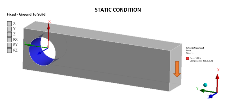
SubscriberLets make it a bit more comprehesive by using the same geometry for both the conditions, i.e. static and then to dynamic.. Since I was not using the same geometry for my previous two examples, it might have become a bit difficult to understand. Observe the first condition below.
CONDITION 1:
 As already discussed, this type of boundary condition is not exactly the same as assumed by the general analytical equations while finding out the max stresses. The flexural formula assumes the fixed boundary condition is applied on the complete cross section at the other end, but lets just consider the above example for now. For initial sizing phase, assume flexural formula can be used to find out the max stresses and then the necessary analytic sizing process is conducted to re-define the size of this structure in order to optimize it for weight. [We haven't reached the FEA yet, just initial sizing].
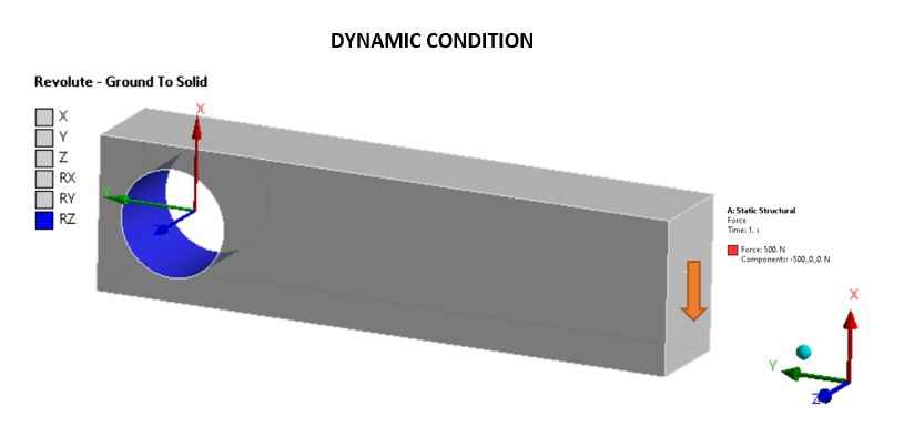
CONDITION 2: (Applied force is a follower force)
 Now how can I size this structure using analytical equations? The structure is flexible in reality, but I don't know how to size this structure to optimize it for weight. [Again, no FEA is involved initially while sizing].
January 14, 2022 at 10:32 pmpeteroznewman
SubscriberCondition 2 is simply an unbalanced rotor. I can imagine a magnet on the tip of the arm with an air gap to a set of stator coils arranged in a circle that generate a tangential force on the tip. For that kind of machine, the analytical equation for the force acting at the shaft center, F = m*r*omega^2 is described in my previous post.
The analytical equation for the dynamics of this system is T = Izz*omegadot where T = F*D, Izz is the mass moment of inertia about the z axis, and omegadot is d(omega)/dt also known as the angular acceleration. Integrate this equation to get omega(t).
The control system that drives the current in the coils in the stator can provide a constant force for only a short time while accelerating the rotor, but at some point, the limits of its ability to continue to accelerate the rotor will be reached and the force will decrease to a point that maintains a steady angular velocity.
At time = 0 when omega = 0, you can do a static structural solution and use inertia relief to show the stress in the arm due to the force at the tip accelerating the flexible body.
January 15, 2022 at 1:00 pmRameez_ul_Haq
Subscriber, well thankyou for the reply.
For that kind of machine, the analytical equation for the force acting at the shaft center, F = m*r*omega^2 is described in my previous post.
At time = 0 when omega = 0, you can do a static structural solution and use inertia relief to show the stress in the arm due to the force at the tip accelerating the flexible body.
Now sir, this is exactly what I wrote. I can find the forces, and also use them to in a FEA static structural solver. But I want to use analytical equations to calculate the STRESS (infact, the max stresses) within my model so that I can size my structure properly by hand first, and then I may go for the FEA. But these equations which should be used for this case to find the stresses, I am unware of them.
January 15, 2022 at 1:10 pmpeteroznewman
SubscriberOnce you have an equation for force, you can use that to calculate stress.
You need to understand the limitations of the equation. For example, the centrifugal force at the center is not equal to the centrifugal force half way along the arm because there is a different amount of mass in the second half of the arm than the first half. It would be more accurate to write the equation as an integral.
January 15, 2022 at 9:53 pmRameez_ul_Haq
SubscriberOnce you have an equation for force, you can use that to calculate stress.
You mean use the same equations for calculation of stress for this case, that we basically use for the static equilibrium case?
January 15, 2022 at 11:55 pmpeteroznewman
SubscriberYes, as long as the force was calculated to include the inertia forces.
January 16, 2022 at 12:36 amViewing 21 reply threads- The topic ‘How will the reaction moment on the support be distributed in terms of forces in this model?’ is closed to new replies.
Innovation SpaceTrending discussionsTop Contributors-
4618
-
1530
-
1386
-
1210
-
1021
Top Rated Tags© 2025 Copyright ANSYS, Inc. All rights reserved.
Ansys does not support the usage of unauthorized Ansys software. Please visit www.ansys.com to obtain an official distribution.
-
The Ansys Learning Forum is a public forum. You are prohibited from providing (i) information that is confidential to You, your employer, or any third party, (ii) Personal Data or individually identifiable health information, (iii) any information that is U.S. Government Classified, Controlled Unclassified Information, International Traffic in Arms Regulators (ITAR) or Export Administration Regulators (EAR) controlled or otherwise have been determined by the United States Government or by a foreign government to require protection against unauthorized disclosure for reasons of national security, or (iv) topics or information restricted by the People's Republic of China data protection and privacy laws.


