Ansys Assistant will be unavailable on the Learning Forum starting January 30. An upgraded version is coming soon. We apologize for any inconvenience and appreciate your patience. Stay tuned for updates.
General Mechanical

General Mechanical

Topics related to Mechanical Enterprise, Motion, Additive Print and more.

How to visualize the layup the section of an element in Mechanical?

    • pnoever
      Subscriber

      Dear all,

      I am struggling to visualize in Workbench somehow the layup of a composite structure in Mechanical. The problem is as follows: I have constructed a composite structure in ACP Pre which is than used in mechanical as shell model. In static structural I get a certain failure with the ACP failure criterion lets say "Max Stress" and it says it is in layer 27. As the structure is pretty complex, it's not that easy to say which is layer 27. How can I plot for this particular element the Layup similar to the LAYPLOT command in APDL?

      Is ACP actually creating layered sections for the shell elements? Or is there anything different behind?

      Appreciate any help you could provide.

      Greetings from Spain!

    • Reno Genest
      Ansys Employee

      Hello,

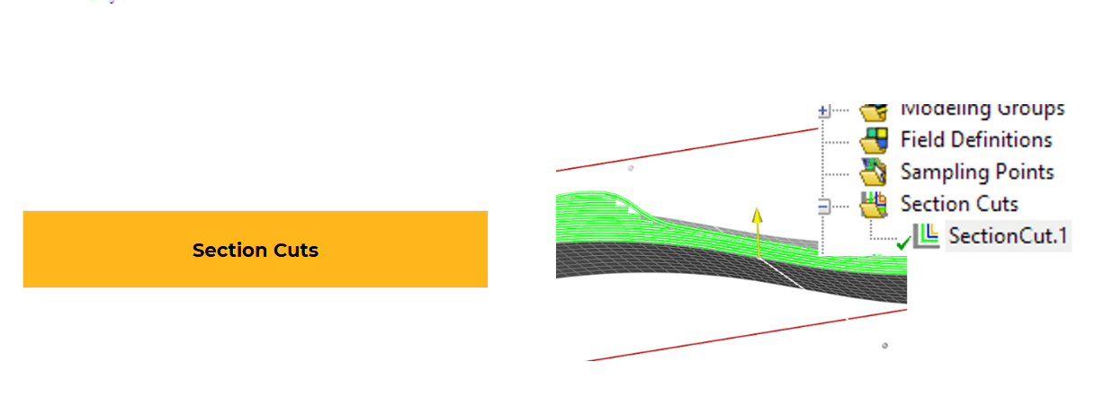
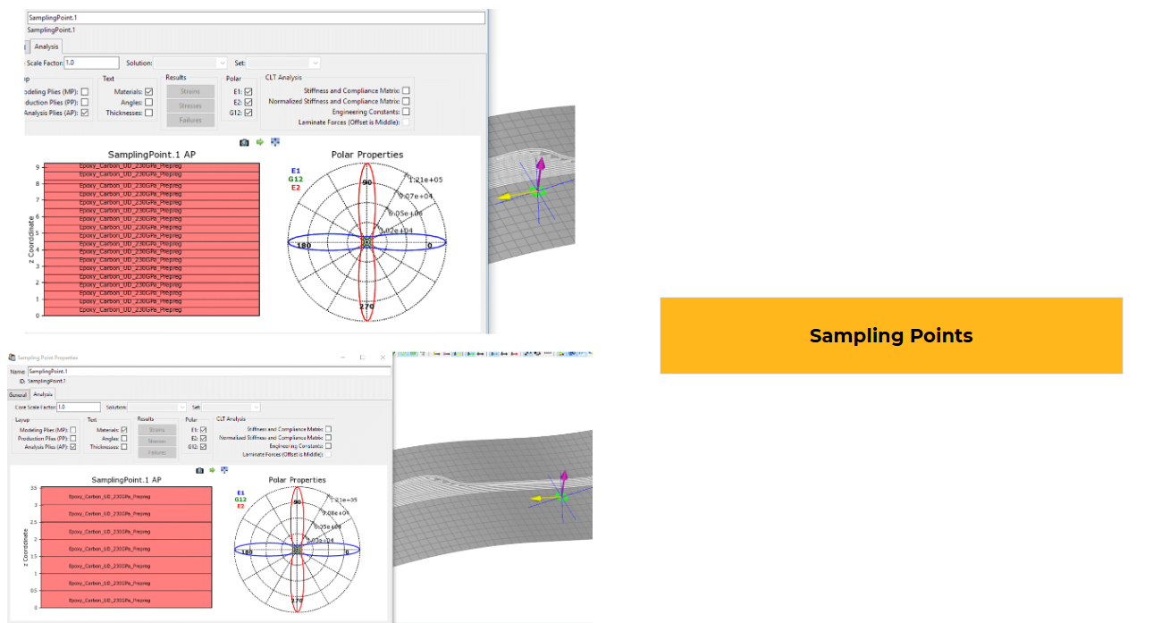
      You can visualize the layup in Ansys Composite PrepPost (ACP) using the following:

      • Section cut.
      • Sampling point.

      There is more information in the Intro to ACP course on the Ansys Learning Hub (ALH):

      Introduction to Ansys Composite PrepPost (ACP) - Ansys Learning Hub


      ACP creates the layered sections for shell elements. You can open the ds.dat file to see what is happening with APDL commands.


      Let me know how it goes.


      Reno.

Viewing 1 reply thread
  • You must be logged in to reply to this topic.
[bingo_chatbox]