-
-
July 10, 2023 at 5:51 pm
sadati
SubscriberHello,
I have the experimental data of the tensile test (displacement as a function of time). I'd like to use the experimental displacement and apply them as a boundary condition in one surface of my model in the Ansys workbench (but not a time-dependent model). Actually, I want to do a displacement control model. But I don't know how can convert the experimental displacements to nodal displacement in Ansys and how can I apply them as a boundary condition on my model. Please help me about it.
Thanks in advance.
-
July 10, 2023 at 7:06 pm
Armin
Ansys EmployeeHi Mahzad,
How the displacement from experiment was measured? Was it measured with an extensometer or is it from the cross-head displacement of the testing machine?
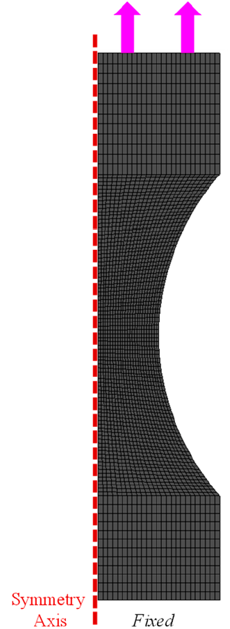
If it is the cross-head displacement, you can simply clamp one end of your tensile specimen model and apply the prescribed displacement to all nodes on surface of the opposite end.
Please see the picture below where a similar specimen is considered (while exploiting symmetry of the geometry): -
July 10, 2023 at 7:15 pm
sadati
SubscriberThanks a lot for your reply.
It is a cross-head displacement. So, should I import the displacement in a CSV format? Do I need to set different time steps?
-
July 10, 2023 at 7:35 pm
Armin
Ansys EmployeeNo problem. As far as I know, the general practice for tensile testing in labs is based on applying a constant cross-head velocity (unless it is a non-monotonic test like tension-compression or fatigue tests). If your experiments were performed with a non-constant velocity, you can input the displacement in a tabular form like you mentioned. You can also employ several steps under "Analysis Settings" to better control each step in your analysis.
-
-
- The topic ‘How to use experimental displacements in a displacement control model’ is closed to new replies.


-
5179
-
1838
-
1387
-
1249
-
1021

© 2026 Copyright ANSYS, Inc. All rights reserved.


