TAGGED: eigensolver-analysis, FDE, losses
-
-
December 4, 2024 at 7:23 amleroy.dokSubscriber
Hello,
I'm trying to understand how to use and relate to the value of the calculated loss in the mode list given by the Eigenmode solver.
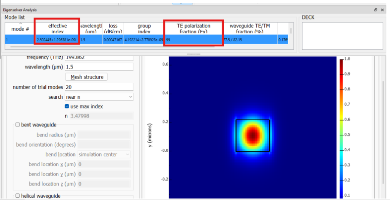
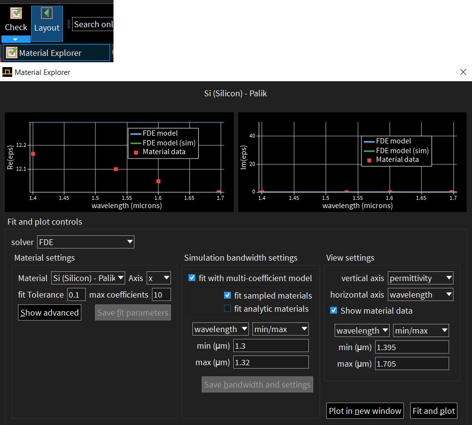
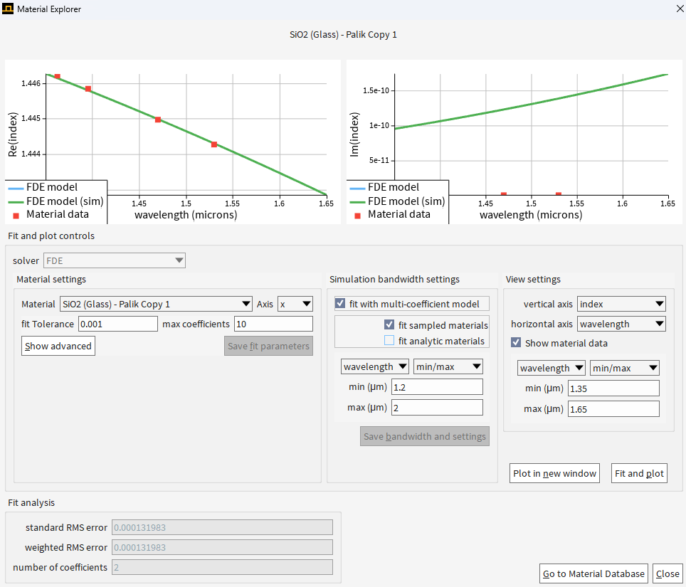
i have simulated a strip waveguide , which has a silicon core and SiO2 cladding (top and bottom). experimentally, and from literature I know that this kind of waveguides are typically suffer from 1-3 dB/cm loss due to propagation losses at 1550 nm wavelengths (for a straight waveguide, no bends) , but I get very low losses (screenshot of the mode list attached).
NOTE: I did not define the waveguide's z span (I left the default value), which in my model is the propagation direction.
I did read the explanation of how MODE calculates the losses, but the result does not make sense to me, as the losses are super low compared to what I expected. (https://optics.ansys.com/hc/en-us/articles/360034396734-FDE-solver-analysis-Mode-List-and-Deck)
Â
Thank you,
Leroy
-
December 4, 2024 at 6:26 pmAmrita PatiAnsys Employee
Hi Leroy,
I think the simplest reason could be that material you are using in your simulation is lossless, however the material could have an imaginary part of the refractive index in reality, contributing to the material absorption/propagation loss. We always recommend checking the "Material Explorer" before running the simulation to make sure that correct values of the real and the imaginary part of permittivity/index are being used by FDE.
We also recommend performing convergence testing to cnfirm the accuracy of different results including the losses. But I will recommend checking the material properties first and then we can talk about convergence testing.
Regards,
Amrita -
December 7, 2024 at 5:23 pmleroy.dokSubscriber
Thank you very much Amrita!
I checked the material explorer and even if I fit the materials it seems like the losses in the mode list still lower than what I expected :
is there anything else that I miss?Â
From my experience the losses should be around -3 dB/cm so the result that I got (0.0004 dB/cm) is very far from that value.
would appriciate your help solving this,
Thank you,
Leroy
Â
-
December 10, 2024 at 10:57 pmAmrita PatiAnsys Employee
Hi Leroy,
Thanks for sharing the screenshot! This looks like silica. Are you using silica in the core, any chance this is the cladding? If any other material is used in the core then you can look at its fit by choosing this material from the "Material" drop-down menu. From this fitting it looks like the imaginary part of the refractive index is close to 0, so I won't expect a lot of losses unless you are simulating a bent waveguide. If you see that material properties of the core material (values reported in literature) are different than the values in the material database, you can try using the "Object Defined Dielectric" and then set the value of n (both real and imaginary) from other sources. The 2nd thing you can do is perform convergence testing to make sure that the values of losses reported by the solver are accurate. This is to make sure that the losses reported by the solver are not impacted by the PML boundaries. So, we run multiple simualtions (could use the sweep utility) increasing the simulation span to minimize modal interactions with PML as much as possible. If you keep increasing the simulation span, the losses should converge beyond a certain point and this should be the accurate loss value.
Regards,
Amrita
-
- You must be logged in to reply to this topic.
- Difference between answers in version 2024 and 2017 lumerical mode solution
- Errors Running Ring Modulator Example on Cluster
- Import material .txt file with script
- Trapezoidal ring
- Help for qINTERCONNECT
- Absorption cross-section of AuNR excited by prism-based TIR
- Issues with getting result from interconnent analysis script
- How to measure transmission coefficients on a given plane .
- Topology Optimization Error
- Edge Coupler EME Example Issue
-
1882
-
802
-
599
-
591
-
366
© 2025 Copyright ANSYS, Inc. All rights reserved.