-
-
November 15, 2023 at 3:45 pm
phuonganhlovely.me
SubscriberI want to simulate a permanent magnet generator (18 slot/ 2 pole), using EDT to design and simulate, but I do not understand how to simulate without load and load for generators.
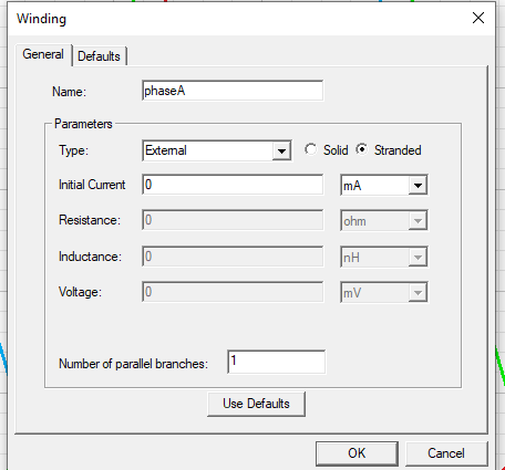
For No-load simulationwhat should i setting here for excitation? Or what do I need to do other than this setting?
For full-load simulation
how can i seeting the excitation for winding?
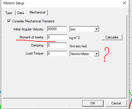
if i want to add load torque (torque applied for examble 5Nm) where can i setting this torque to simulation? i am try to setting load torque like fig bellow but it is require moment of initial too. is it correct?
how can i calculate the load ( resistance) to simulation to get the current i desire ( my taget 30kw and 48A at full load, 60000rpm)
-
November 17, 2023 at 8:55 am
Harinath Vudumula
Ansys EmployeeHellow,
You can follow below steps.
For no load simulation of Generator :
- Cnahge the ecxitation type to Current and you can give current as Zero (0 A).
- Run the simulation. We can find out here no load induced voltage, no load core loss and cogging torque.
For Full load Simulation of Generator:
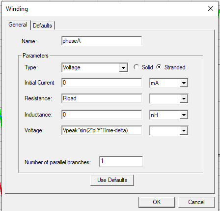
- Change the ecxitation type as voltage, enter the winding resistance and end winding leakage inducthance values.
- we can use voltage experssion which given below.
- 1. Solution:Va= Vpeak*sin(2*pi*f*Time-delta),Vb= Vpeak*sin(2*pi*f*Time-120deg-delta),Vc= Vpeak*sin(2*pi*f*Time-240deg-delta). Condition: no load induced voltage of phase a has to be zero at 0 sec. we can do parametric setup on delta variable or if you know the delta (load angle) you can enter the value in degrees.This type of setup will not consider mechanical transients, just speed is enough. (or)
- 2. Solution:If you want to consider mechanical transients, your approuch is correct. But Moment of inertia is required and load torque is 4.7746 Nm as per the input provided by you. Va= Vpeak*sin(2*pi*f*Time),Vb= Vpeak*sin(2*pi*f*Time-120deg),Vc= Vpeak*sin(2*pi*f*Time-240deg).(or)
- 3. Solution:we can get load resistance from per phase power and per phase current. consider your machine has 3 phase and connected in star. Then Rl=(per phase power)/(per phase current)^2= 10000/(48)^2 =4.34027 ohm. Enter the (4.34027+winding resistance) in resistance tab in excitation window. Va=0, Vb=0 and Vc=0.
Hope it will help you.
Thank you,
Harinath Vudumula.
-
November 20, 2023 at 11:47 am
phuonganhlovely.me
SubscriberThank you Harinath Vudumula.I appreciate the way you explained the steps for the 2 simulation cases.I also have some questions I want to clarify.1. solution (1): how to determine the value of Vpeak?2. Solution (2): why the load torque is 4.7746 Nm while I want to apply 5 Nm (load torque) (when I set the moment of inertia value the speed also increases) and Why doesn't the voltage equation have a delta variable?3. solution (3): how can I connect the coil in the star (do you mean using group winding?)thank you so much -
November 20, 2023 at 12:12 pm
Harinath Vudumula
Ansys EmployeeHellow,
- how to determine the value of Vpeak? Ans: It depends on you design, at what voltage you are going to operate the machine.
- why the load torque is 4.7746 Nm while I want to apply 5 Nm (load torque) (when I set the moment of inertia value the speed also increases) and Why doesn't the voltage equation have a delta variable? Ans: As per the data given by you (30kW and 60000rpm), if you back calculate torque it will be 4.7746 Nm. if you want to give 5 Nm, you can give. If you consider the mechanical transients in motion setup we need to check the results in the steady state. The speed may increase or decrease, it will depends on the setup and speed will settledown in steady state. The variable delta is not required if you consider mechanical transients, the rotor position will adjust as per the load.
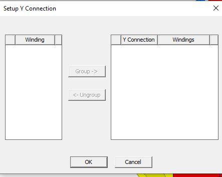
- how can I connect the coil in the star (do you mean using group winding?) Ans: Yes
Thank you,
Harinath Vudumula.
-
November 21, 2023 at 3:48 pm
phuonganhlovely.me
SubscriberThank you Harinath Vudumula.
1. my design is run as 2 modes
mode 1: motor mode ( for the begining) the voltage input is 380 Vac
mode 2: generator mode (after achive the speed) (full load voltage 380 Vac, 48A, 30Kw)
so the Vpeak here is 380 Vac, is it correct? (Vpeak is the phase voltage or line voltage)
3. connect the coil in the star It depends on the ecxitation type ? because i do not see any winding in the set up Y connection in excitation type of current ( when i simulation no load condition), only ecxitation type as voltage just need this setting?
thank you so much
-
November 22, 2023 at 4:04 am
Harinath Vudumula
Ansys EmployeeHello,
- we need to enter Peak value of phase voltage in voltage tab of windings. Please get the information about the voltage. Is 380 V RMS line/phase voltage or peak line/phase voltage?
- connect the coil in the star It depends on the ecxitation type ? Ans: yes, if it is voltage as excitation we can use this option.
Thank you,
Harinath Vudumula.
-
December 4, 2023 at 5:34 am
phuonganhlovely.me
Subscriberthank Harinath Vudumula,
- as i have mention my design will be run as 2 mode but the major one is generator. so at full load condition ( 60,000 rpm, 5Nm and resistance load) if I want to avchieve output line voltage 380V (380V is rms of line voltage), 48A, 30KW. I need to enter Peak value of phase voltage in the equation (ex: Va= Vpeak*sin(2*pi*f*Time-delta) ) Vpeak = (380*sqrt(2)) / sqrt(3) =310V, is this correct?
thanks a lot
-
December 4, 2023 at 6:31 am
Harinath Vudumula
Ansys EmployeeHello,
Yes, 310 V is correct for phase peak voltage.
Thank you,
Harinath Vudumula.
-
December 4, 2023 at 7:34 am
phuonganhlovely.me
SubscriberThank Harinath Vudumula,
- when excitation for winding (like fig below) we also have to enter the value of resisance in resistance tap. what is this resistance come from ? and what difference between solution 1 compare with solution 3, because we also need to enter the value of resistance as a load.
2. I have another question, how to calculate winding resistance on the ansys EDT ?
because in the revious answer you said input resistance load + winding resistance in resistance box. ( how about inductance box?) i am confuse it.
Thanks a lot.
-
- The topic ‘How to simulation no- load and full load PM generator’ is closed to new replies.


-
4888
-
1587
-
1386
-
1242
-
1021

© 2026 Copyright ANSYS, Inc. All rights reserved.


