TAGGED: fouling, porous-media, shadow-interface, wall-shadow, water-filter
-
-
October 26, 2021 at 3:17 pm
hhayati
SubscriberHello,
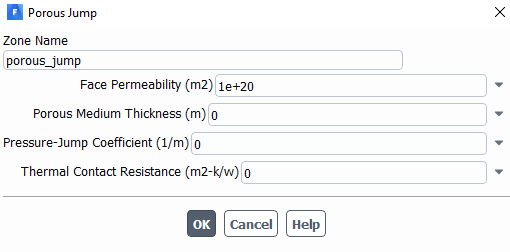
I am trying to simulate particle transport in a filter (filter fouling) and I used Porous Media in Fluent to simulate fluid flow.
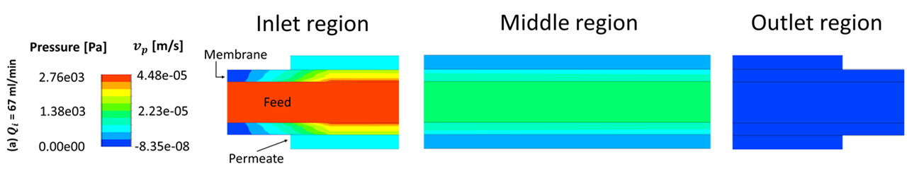
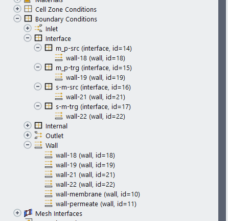
The geometry has 3 zones-feed zone, membrane zone, and permeate zone. Fluent generates shadow walls associated to the interface between these zones. My issue is that apparently particles cannot deposit on the shadow walls, although I set "Trap" boundary condition for them! Particles cross the porous media and reach permeate zone, which is wrong!
Has anybody worked on this before? If so, would you let me know what the solution is?
Best,
October 26, 2021 at 3:55 pmRob
Forum ModeratorIf Fluent is creating walls at these locations you'll not get any flow either. Can you check the model set up? Please post a few images of the pressure & velocity field.
October 26, 2021 at 4:56 pmOctober 27, 2021 at 10:38 amRob
Forum ModeratorYou're looking at wall-18, wall-19 etc? Those are part of the interface zone and only exist if there are only cells on one side of the interface. If you have cells on both sides of the interface (ie 100% contact) the wall isn't present. A wall, wall-shadow pair is for a wall boundary with cells on both sides but also a conformal mesh.
October 27, 2021 at 1:45 pmhhayati
SubscriberYes, I have cells on both sides. And, I do have conformal mesh. Based on what you sad ("the wall isn't present"), then particles can not deposit on these interfaces, right? even if I set trap boundary condition for them.
October 28, 2021 at 11:22 amRob
Forum ModeratorCorrect as there isn't a wall. If you remesh with a conformal mesh you can make those surfaces into a porous jump and those can trap particles.
October 29, 2021 at 2:31 pmhhayati
SubscriberThank you so much .
I am a bit confused.
can I consider the membrane zone as porous media and its boundaries as porous jump?
October 29, 2021 at 2:40 pmRob
Forum ModeratorIf the membrane is a porous media you set the properties on that. You use a PJ as the bounding surface and ensure resistance is zero, but use it to assign particle bc's.
October 29, 2021 at 3:20 pmOctober 29, 2021 at 4:10 pmRob
Forum ModeratorCan you post the new results?
November 3, 2021 at 1:54 pmhhayati
SubscriberThank you @rob. It worked out for the fluid domain and gave correct fluid flow.
Another issue that I am facing now is that in particle deposition UDFs I need to introduce porous jump thread and face.
All the UDFs are developed for walls, but when I hook them to my current simulation, the particle tracking won't work! I could not find out how to introduce porous jump thread and face to the UDFs!
Would you let me know how I can do that?
November 3, 2021 at 2:51 pmRob
Forum ModeratorYou can use PJ zones, but it's a bit more advanced. However, we're also very limited in what we can cover on here, so all I can say is read the UDF manual.
July 18, 2023 at 9:43 amFluent User
SubscriberHello,
why to use a zone for permeate?
Best wishes
July 19, 2023 at 2:15 pmFluent User
SubscriberHello, you have chosen the inlet region according to the startup length? How have you fixed the 3 regions (inlet, middle, outlet)? or is it only for post-proceeding? Best wishesViewing 13 reply threads- The topic ‘How to Simulate Particle Deposition on Membrane Surface’ is closed to new replies.
Ansys Innovation SpaceTrending discussionsTop Contributors-
3150
-
1013
-
956
-
858
-
797
Top Rated Tags© 2025 Copyright ANSYS, Inc. All rights reserved.
Ansys does not support the usage of unauthorized Ansys software. Please visit www.ansys.com to obtain an official distribution.
-