
-
-
December 27, 2020 at 4:51 pm
Ayman
SubscriberI tried to simulate this attached research to study a new bolt under a moment connection
December 27, 2020 at 11:00 pmpeteroznewman
Subscribern#1 To answer this question, I would have to read [19] R.M. Sully, G.J. Hancock, Behavior of cold-formed SHS beam-columns, J. Struct. Eng. ASCE 122 (3) (1996) 326?336.n#2 The loading plate can be defined as rigid.n#3 There is no Tie command in ANSYS. You can find that command in ABAQUS. In ANSYS that could be the CEINTF command, but it is simpler to use Bonded Contact.n#4 This is a two-step analysis. In step 1, the axial load is applied to compress the column. In step 2, the tip load is applied.nDecember 28, 2020 at 5:57 pmSubscriber#1 n#2 I can't understand exactly what he meaning by loading plate did he mean the force applied in the beam arm or the axial force acting on the column if you see my model I have applied a remote displacement to simulate the axial fore of the column and I have sliced the face of the beam to insert a force on beam arm so did I need to do more.nAnother question of how could I draw the moment rotation curve in ansys the research explained some rules to draw the curve n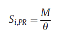 n
n
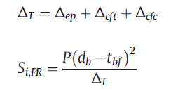
 but I don't know how to evaluate these resultsn1- (P) n2-(Δep) when should I select probe deformation geometry to calculate endplate deformationn3-(Δcft) when should I select probe deformation geometry to calculate column tension deformationn4-(Δcfc) when should I select probe deformation geometry to calculate column compression deformationnand I have attached my model if anything I have to do please tell me.nthank you for your response.nbest regards; nAymannn
December 28, 2020 at 10:42 pmSubscriberArrayn#1 I read [19] Sully and Hancock, who show residual stress was measured in the flat sections only, where membrane stress was almost zero and bending stress was almost yield. While zero residual stress was used in their FEA model. I could not find anything resembling the claim by Tahir et al of residual stress of 0.4fy and (0.24–0.0006B) fy in the Sully paper.n#2 A remote force with behavior set to Rigid acting axially on the column is what is intended. You are good to go there.nYou will have to figure out how to extract the moment rotation curve. I am not an expert at this, though I have helped another member try to understand this in another discussion.n/forum/discussion/2074/getting-the-moment-that-the-beam-transfer-to-the-column-modelling-with-solids-porticnnDecember 30, 2020 at 6:27 pmSubscriber#1 I am trying to search again about this point.n#2 He explains that Pp The yield load of the endplate and column flange need to be calculated based on the yield line mechanisms and the least value is selected as Pp. so can you guide me to how could I calculate them?nbest regards;nAymaJanuary 4, 2021 at 6:27 pmSubscriber@peteroznewmannDear peternI tried to run the model but I still have error and warning messages if you can help me to solve them I have attached my model if you can check it.nnerror:n#1 The solver engine was unable to converge on a solution for the nonlinear problem as constrained. Please see the Troubleshooting section of the Help System for more information.nwarning:n#1 The solution failed to solve completely at all time points. Restart points are available to continue the analysis. n#2 Although the solution failed to solve completely at all time points, partial results at some points have been able to be solved. Refer to Troubleshooting in the Help System for more details.n#3 The unconverged solution (identified as Substep 999999) is output for analysis debug purposes. Results at this time should not be used for any other purpose.n#4 Solver pivot warnings or errors have been encountered during the solution. This is usually a result of an ill conditioned matrix possibly due to unreasonable material properties, an under constrained model, or contact related issues. Check results carefully.n#5 Contact status has experienced an abrupt change. Check results carefully for possible contact separation.n#6 One or more MPC contact regions or remote boundary conditions may have conflicts with other applied boundary conditions or other contact or symmetry regions. This may reduce solution accuracy. Tip: You may graphically display FE Connections from the Solution Information Object for non-cyclic analysis. Refer to Troubleshooting in the Help System for more details.n#7 Two or more remote boundary conditions are sharing a common face, edge, or vertex. This behavior can cause solver overconstraint and is not recommended, please check results carefully. You may select the offending object and/or geometry via RMB on this warning in the Messages window.n#8 An all-quad-free face mesh type was chosen, but some triangles were created during meshing.n#9 One or more objects may have lost some scoping attachments during the geometry update. You can identify these tree objects by filtering the tree using the Scoping option set to Partial.nn nJanuary 5, 2021 at 3:24 amSubscriberFebruary 3, 2021 at 9:33 amSubscriber@peteroznewmannDear Peter,nI have followed your above instructions and it was really helpful after that I have tried to use symmetry in the XY plane to reduce time but I have some errors and warning:n1- Current result file may not contain requested result data \Master\Varification model\I-beam to square hollow column blind bolted moment connection Experimental and numerical study8_files\dp0\SYS\MECH\file.rst. Please clear the solution and solve again.n2-The result file \Master\Varification model\I-beam to square hollow column blind bolted moment connection Experimental and numerical study8_files\dp0\SYS\MECH\file.rst cannot be opened.n3-Element violations were found by the solver. Named selections have been added for these elements.n4- The solver engine was unable to converge on a solution for the nonlinear problem as constrained. Please see the Troubleshooting section of the Help System for more information.n5- The solver did not generate valid result files so the Newton-Raphson Residuals for the incomplete solution cannot be loaded.n6- Element 21344 located in Body B3M20 (and maybe other elements) has become highly distorted. You may select the offending object and/or geometry via RMB on this warning in the Messages window. Excessive distortion of elements is usually a symptom indicating the need for corrective action elsewhere. Try incrementing the load more slowly (increase the number of substeps or decrease the time step size). You may need to improve your mesh to obtain elements with better aspect ratios. Also consider the behavior of materials, contact pairs, and/or constraint equations. If this message appears in the first iteration of first substep, be sure to perform element shape checking. Named Selections for the offending element can be created via the Identify Element Violations property on the Solution Information Object.n7- One or more MPC contact regions or remote boundary conditions may have conflicts with other applied boundary conditions or other contact or symmetry regions. This may reduce solution accuracy. Tip: You may graphically display FE Connections from the Solution Information Object for non-cyclic analysis. Refer to Troubleshooting in the Help System for more details.n
but I don't know how to evaluate these resultsn1- (P) n2-(Δep) when should I select probe deformation geometry to calculate endplate deformationn3-(Δcft) when should I select probe deformation geometry to calculate column tension deformationn4-(Δcfc) when should I select probe deformation geometry to calculate column compression deformationnand I have attached my model if anything I have to do please tell me.nthank you for your response.nbest regards; nAymannn
December 28, 2020 at 10:42 pmSubscriberArrayn#1 I read [19] Sully and Hancock, who show residual stress was measured in the flat sections only, where membrane stress was almost zero and bending stress was almost yield. While zero residual stress was used in their FEA model. I could not find anything resembling the claim by Tahir et al of residual stress of 0.4fy and (0.24–0.0006B) fy in the Sully paper.n#2 A remote force with behavior set to Rigid acting axially on the column is what is intended. You are good to go there.nYou will have to figure out how to extract the moment rotation curve. I am not an expert at this, though I have helped another member try to understand this in another discussion.n/forum/discussion/2074/getting-the-moment-that-the-beam-transfer-to-the-column-modelling-with-solids-porticnnDecember 30, 2020 at 6:27 pmSubscriber#1 I am trying to search again about this point.n#2 He explains that Pp The yield load of the endplate and column flange need to be calculated based on the yield line mechanisms and the least value is selected as Pp. so can you guide me to how could I calculate them?nbest regards;nAymaJanuary 4, 2021 at 6:27 pmSubscriber@peteroznewmannDear peternI tried to run the model but I still have error and warning messages if you can help me to solve them I have attached my model if you can check it.nnerror:n#1 The solver engine was unable to converge on a solution for the nonlinear problem as constrained. Please see the Troubleshooting section of the Help System for more information.nwarning:n#1 The solution failed to solve completely at all time points. Restart points are available to continue the analysis. n#2 Although the solution failed to solve completely at all time points, partial results at some points have been able to be solved. Refer to Troubleshooting in the Help System for more details.n#3 The unconverged solution (identified as Substep 999999) is output for analysis debug purposes. Results at this time should not be used for any other purpose.n#4 Solver pivot warnings or errors have been encountered during the solution. This is usually a result of an ill conditioned matrix possibly due to unreasonable material properties, an under constrained model, or contact related issues. Check results carefully.n#5 Contact status has experienced an abrupt change. Check results carefully for possible contact separation.n#6 One or more MPC contact regions or remote boundary conditions may have conflicts with other applied boundary conditions or other contact or symmetry regions. This may reduce solution accuracy. Tip: You may graphically display FE Connections from the Solution Information Object for non-cyclic analysis. Refer to Troubleshooting in the Help System for more details.n#7 Two or more remote boundary conditions are sharing a common face, edge, or vertex. This behavior can cause solver overconstraint and is not recommended, please check results carefully. You may select the offending object and/or geometry via RMB on this warning in the Messages window.n#8 An all-quad-free face mesh type was chosen, but some triangles were created during meshing.n#9 One or more objects may have lost some scoping attachments during the geometry update. You can identify these tree objects by filtering the tree using the Scoping option set to Partial.nn nJanuary 5, 2021 at 3:24 amSubscriberFebruary 3, 2021 at 9:33 amSubscriber@peteroznewmannDear Peter,nI have followed your above instructions and it was really helpful after that I have tried to use symmetry in the XY plane to reduce time but I have some errors and warning:n1- Current result file may not contain requested result data \Master\Varification model\I-beam to square hollow column blind bolted moment connection Experimental and numerical study8_files\dp0\SYS\MECH\file.rst. Please clear the solution and solve again.n2-The result file \Master\Varification model\I-beam to square hollow column blind bolted moment connection Experimental and numerical study8_files\dp0\SYS\MECH\file.rst cannot be opened.n3-Element violations were found by the solver. Named selections have been added for these elements.n4- The solver engine was unable to converge on a solution for the nonlinear problem as constrained. Please see the Troubleshooting section of the Help System for more information.n5- The solver did not generate valid result files so the Newton-Raphson Residuals for the incomplete solution cannot be loaded.n6- Element 21344 located in Body B3M20 (and maybe other elements) has become highly distorted. You may select the offending object and/or geometry via RMB on this warning in the Messages window. Excessive distortion of elements is usually a symptom indicating the need for corrective action elsewhere. Try incrementing the load more slowly (increase the number of substeps or decrease the time step size). You may need to improve your mesh to obtain elements with better aspect ratios. Also consider the behavior of materials, contact pairs, and/or constraint equations. If this message appears in the first iteration of first substep, be sure to perform element shape checking. Named Selections for the offending element can be created via the Identify Element Violations property on the Solution Information Object.n7- One or more MPC contact regions or remote boundary conditions may have conflicts with other applied boundary conditions or other contact or symmetry regions. This may reduce solution accuracy. Tip: You may graphically display FE Connections from the Solution Information Object for non-cyclic analysis. Refer to Troubleshooting in the Help System for more details.n Viewing 7 reply threads
- The topic ‘how to simulate HSS to I BEAM BOLTET CONNECTION?’ is closed to new replies.
Innovation Space Trending discussions
 Top Contributors
-
peteroznewman
 5734
5734 -
scabo
 1906
1906 -
Dennis Chen
 1419
1419 -
javat33489
 1305
1305 -
Shyam Prasad V Atri
1021
Top Rated Tags
© 2026 Copyright ANSYS, Inc. All rights reserved.
Ansys does not support the usage of unauthorized Ansys software. Please visit www.ansys.com to obtain an official distribution.
-


The Ansys Learning Forum is a public forum. You are prohibited from providing (i) information that is confidential to You, your employer, or any third party, (ii) Personal Data or individually identifiable health information, (iii) any information that is U.S. Government Classified, Controlled Unclassified Information, International Traffic in Arms Regulators (ITAR) or Export Administration Regulators (EAR) controlled or otherwise have been determined by the United States Government or by a foreign government to require protection against unauthorized disclosure for reasons of national security, or (iv) topics or information restricted by the People's Republic of China data protection and privacy laws.

Please Login to Report Topic
Please Login to Share Feed
Edit Discussion
The Ansys Learning Forum is a public forum. You are prohibited from providing (i) information that is confidential to You, your employer, or any third party, (ii) Personal Data or individually identifiable health information, (iii) any information that is U.S. Government Classified, Controlled Unclassified Information, International Traffic in Arms Regulators (ITAR) or Export Administration Regulators (EAR) controlled or otherwise have been determined by the United States Government or by a foreign government to require protection against unauthorized disclosure for reasons of national security, or (iv) topics or information restricted by the People's Republic of China data protection and privacy laws.