TAGGED: cfx-tracer-simulation
-
-
October 15, 2024 at 5:23 pm
Kelsey O'Donnell
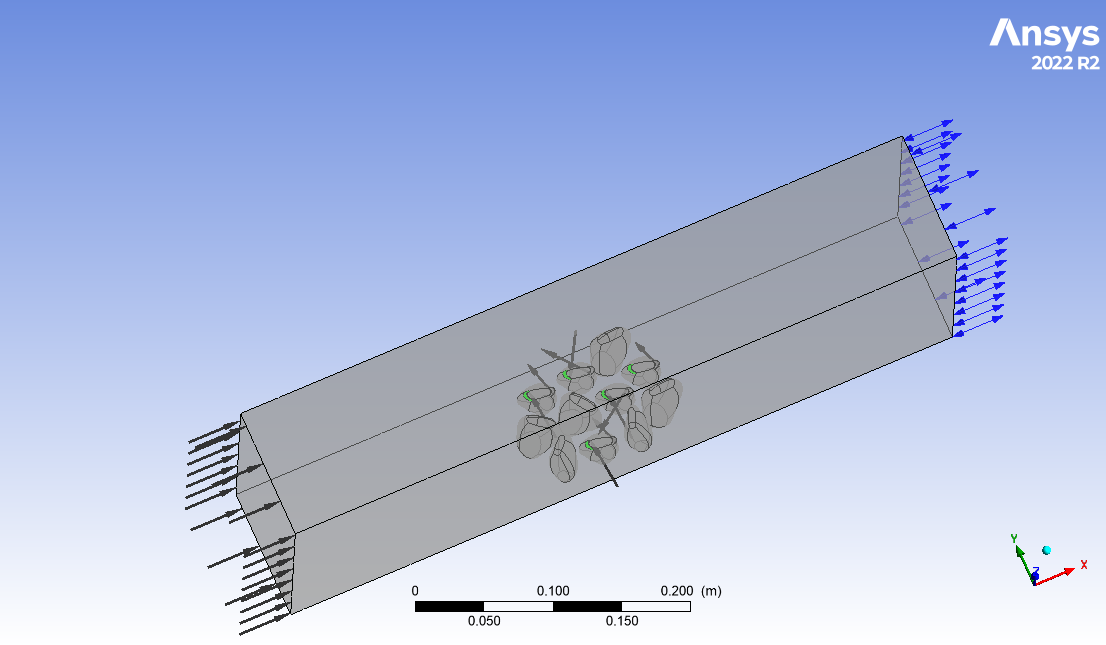
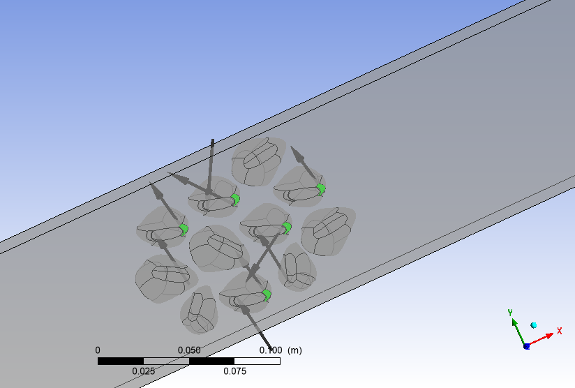
SubscriberI would like to simulate how the overall concentration of a tracer varies in a large fluid domain (like a flume) through both mixing due to a set of rigid structures and through the consumption of the tracer by some of these objects. I have an aggregation of 12 objects, five of which have been turned into pumps with an internal volume and set inlet and outlet boundary conditions (with a velocity inlet and zero pressure opening for the outlet). I would like to set an ambient level of tracer in my larger velocity inlet for the whole rectangular fluid domain and then have the fluid enter the small inlet with that ambient level of tracer but with a level of consumption (i.e. 10% of what enters) at the outlet. I am not sure how to do this given the current options for adding in an additional variable to use as a tracer. Does anyone have any suggestions as to how I might do this? I have included a photo of my geometry, the smaller inlets and outlets are highlighted in green.

-
October 16, 2024 at 9:10 am
Rob
Forum ModeratorIf you use species as your tracer (water and water-tracer as an example) you also want inlet/outlets on the objects (mussels?). Look at expressions, so object-inlet just removes all mass and object outlet has an expression for species fraction that's (for example) [0.5 x inlet concentration] Assuming the object in & out are matched then you can use velocity bc's on both surfaces and I'd use mass-weighted to find the species fraction on a flow boundary.
-
October 16, 2024 at 7:00 pm
Kelsey O'Donnell
SubscriberHi Rob, thank you for your reply. Currently I am using an additional variable (as added and set up in CFX pre) as my "tracer". I have assigned it a diffusivity coefficient of 1.2e-9 and selected the diffusive transport equation to be solved. I also set the following boundary conditions:
Domain intialization: 0 kg/m^3 for tracer value
Velocity large inlet (on left of rectangular fluid domain): Velocity of 1 cm/s and tracer value of 0.1 kg/m^3
Velocity large outlet: Set as 0 Pa opening with zero flux
Mussel inlets: Velocity of 0.89 cm/s and tracer value of 0.05 kg/m^3
Mussel outlets: Velocity of 1 cm/s and tracer value of 0.025 kg/m^3
The mussel outlet and inlet are connected as the solid object has a fluid volume extracted from it and the outlet face area is 89% of the inlet face area hence the ratio of velocities (to maintain conservation of mass)
Will this setup work or do I need to create a species and use that as my tracer as you suggested? I am not sure what expressions I should be creating for my mussel Inlet and outlet.
-
-
October 17, 2024 at 10:52 am
Rob
Forum ModeratorNot sure as I don't use CFX. At a CFD common sense level it looks more-or-less fine.
The mussel inlet shouldn't care what the tracer concentration is, but the mussel outlet should have tracer as a function of the inlet value: otherwise you're not accounting for recirculation effects.
-
October 17, 2024 at 11:02 am
Mark O
Ansys EmployeeIt should work fine as a tracer. The tracer value will not get used on an opening unless flow comes back in. If the mussel inlet and outlet are connected then you should also set the tracer values consistent with conservation minus whatever level of consumption you wish to simulate.
-
October 18, 2024 at 2:45 pm
Kelsey O'Donnell
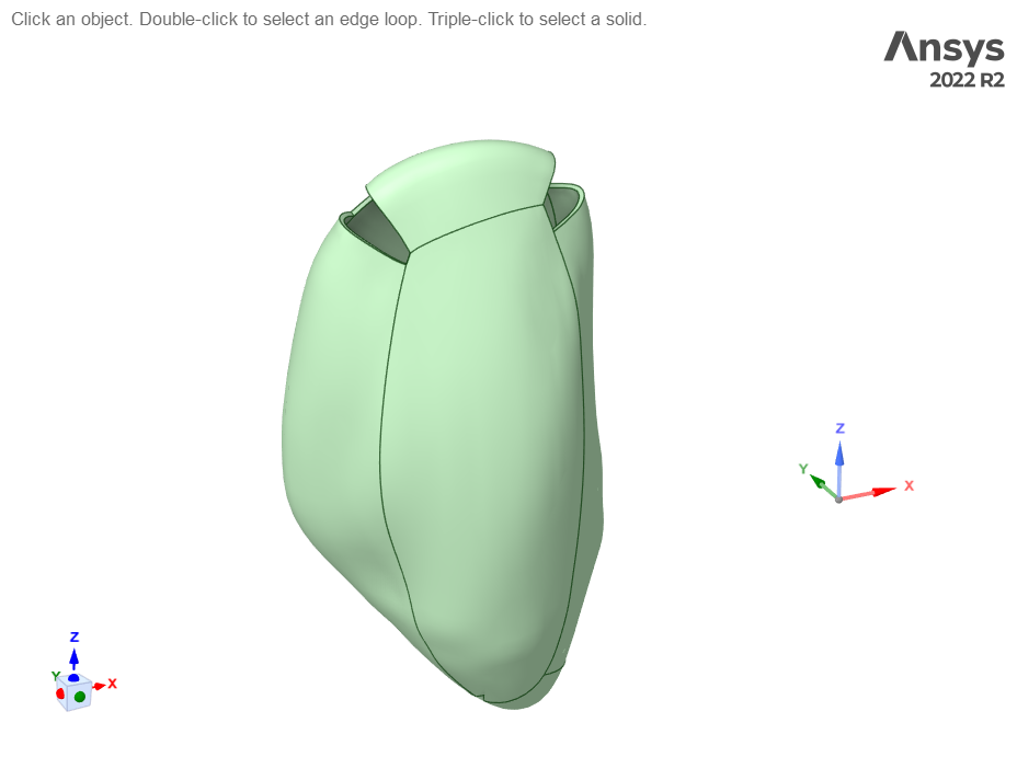
SubscriberHi Mark, thank you for the reply. I wonder if I am initially setting up the geometry correctly? The way that I have it currently is with the mussel geometry as such:

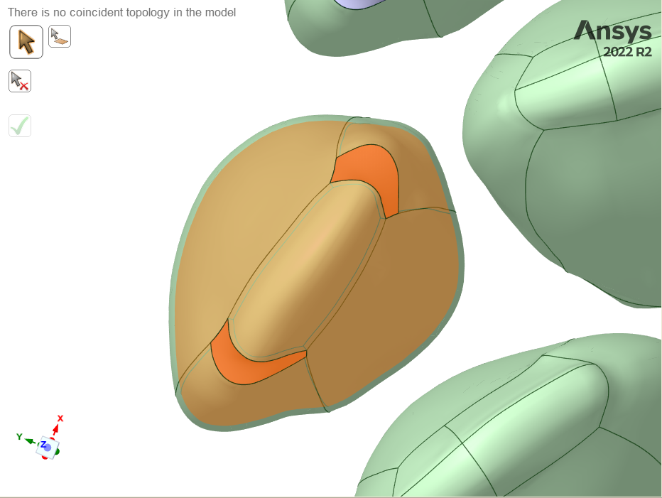
And from here I then extract the volume from the internal cavity (volume shown highlighted in orange)
I am now having some issue creating an enclosure around this (though I didnt initially) and I am wondering if perhaps this is not how I should turn the mussel geomtry into a "pump" with internal flow that can then be placed in a large aggregation that is placed into an enclosure for simulatenous external flow. I simply deleted the "inlet" and "outlet" faces from my original body and then pulled all other faces in order to creat a solid body with an internal cavity. Is this the proper setup or should I be creating my geometry differently?
-
-
October 18, 2024 at 2:59 pm
Mark O
Ansys EmployeeHi Kelsey, it looks a little tricky because of the underlying CAD geometry but you look to be doing the correct thing. To create the orange region it may be better to create some capping surfaces and then fill by capping. Once you have the orange volume region you need to subtract it from the rest of the volume. In DesignModeler you would do a boolean subtract and select the two solids. In Spaceclaim you would use the combine tool.
-
- You must be logged in to reply to this topic.


-
5179
-
1837
-
1387
-
1249
-
1021

© 2026 Copyright ANSYS, Inc. All rights reserved.


