-
-
January 23, 2024 at 5:47 am
ssy6225
SubscriberPaper Name: SiN-assisted flip-chip adiabatic coupler between SiPh and Glass OPCBs
I'm doing a simulation by referring to the paper.
I am conducting simulations using the MODE solver for adiabatic coupling in a glass waveguide with an Si inverse taper in EME. However, I am facing an issue where the red markers, as shown in the figure below, are not appearing on the monitor and EME, leading to no results. I would like to resolve this issue.
+ I would like to know how to set up the ports for simulation, as illustrated in the figure, where there is a glass waveguide and an Si taper on one side. I would appreciate guidance on configuring the ports for this simulation.
-
January 24, 2024 at 9:51 am
Niki Papachristou
Ansys EmployeeHi 석영 신,
Thank you for reaching out to us and for attaching images of your simulation! I am afraid I still don't understand what are the red markers, is it a structure in the object tree? As for the ports you can find more information here: Ports (FDTD) - Simulation Object
Kind Regards,
Niki
-
- The topic ‘
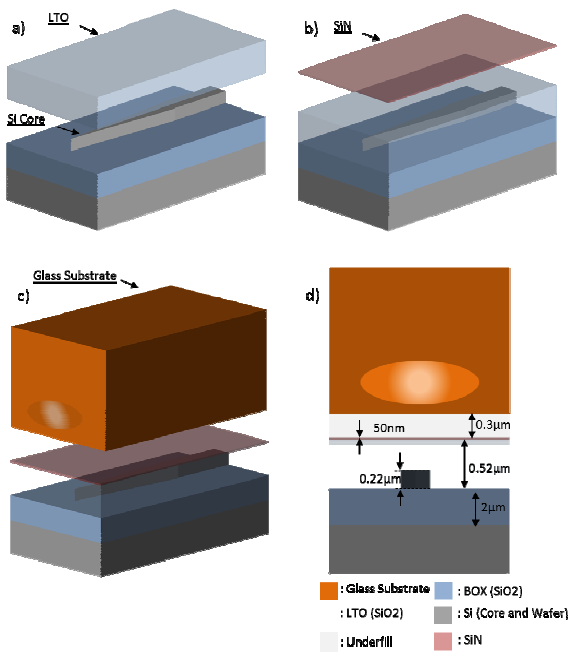
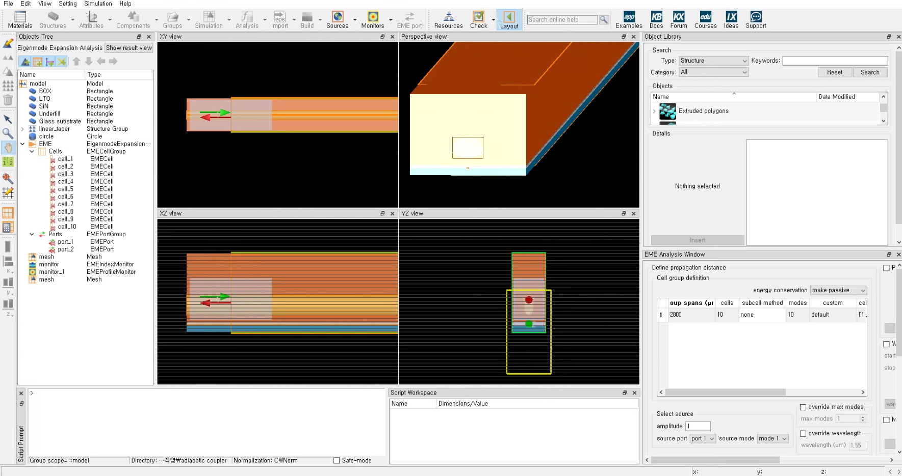
How to Simulate Adiabatic Coupler with MODE solver EME’ is closed to new replies.
- Import material .txt file with script
- Errors Running Ring Modulator Example on Cluster
- Absorption cross-section of AuNR excited by prism-based TIR
- How to measure transmission coefficients on a given plane .
- TE Polarization Fraction + Waveguide TE/TM Fraction
- Edge Coupler EME Example Issue
- Lumerical Python API Topology Optimization Error 2025 R1
- 2D inverse design grating coupler
- FDE : Simulation waveguides with electrodes
- Loss of lithium niobate phase modulator
-
2262
-
925
-
599
-
591
-
497
© 2025 Copyright ANSYS, Inc. All rights reserved.