-
-
October 28, 2017 at 3:01 pm
Vinod Kumar
SubscriberHello all,
I am doing my FYP under title as entitled above, in this simulation our objective is to find the the rotational speed and maximum power with variation of flow depth.
I am unable to start my simulation, I've got problems with defining boundary conditions, unnecessary boundaries are being created(image attached.). Kindly help me out. Give some guideline to start.
Thankyou.
Â
Â
Â
-
October 28, 2017 at 3:07 pm
Raef.Kobeissi
SubscriberHello VINOD It appears to me that you have multiple objects that are sharing interfaces between each other (contact region). You have to make sure that contact regions between fluid objects or fluid-solid objects should be assigned as ‘Interfaces’ and you need to couple them in the Interface Window.
Cheers -
October 28, 2017 at 3:12 pm
Vinod Kumar
SubscriberThanks for your kind reply, I am new to Ansys. Kindly share some material/videos that could help me in this regard, if you can.
-
October 28, 2017 at 3:15 pm
Vinod Kumar
SubscriberI've watched your tutorial "https://www.youtube.com/watch?v=8NIOC8Nl91E&t=30s" here you start directly with fluent. I'd like to know about the initial steps of your tutorial.Â
-
October 28, 2017 at 3:15 pm
Raef.Kobeissi
SubscriberHi Vinod Have a look at this tutorial, you can use a similar methodoly to simulate Turbines but you need to remember to use the VOF Multiphase model:
Also, I have a wide range of tutorials on my channel which could help you solve your problem, please have a look here:
https://www.youtube.com/TheFiravia -
October 28, 2017 at 3:19 pm
Raef.Kobeissi
SubscriberThe initial steps is to create your geometry and then mesh. You can find many tutorials on modeling and meshing by visiting ANSYS How To youtube channel and also visit my channel for a lot of examples:
https://www.youtube.com/user/ANSYSHowToVideos
https://www.youtube.com/TheFiravia -
October 28, 2017 at 3:26 pm
-
November 4, 2017 at 12:59 pm
Vinod Kumar
SubscriberDear Raef Koebessi, I've only one question regard boundary condition.
In you tutorial, you're defining mesh interface(b/w domain & inner domin) to interior, while you didn't even named it as interior or anything else.Â
In my case this interface are being read as a wall (I am using "read multiple mesh file" technique).
-
November 4, 2017 at 8:52 pm
Raef.Kobeissi
SubscriberHi!
There is a slight difference between 2D and 3D simulation. My simulation was a 2D model therefore the interface between the 2 domain has been automatically allocated as interior. For your case I would auggest not to create 2 domain but only one which encompasses the wall of the turbine.
Cheers -
November 7, 2017 at 2:12 pm
Vinod Kumar
Subscriber
This image is the result after flow time 1.196s, I am worried about it's orientation. Kindly guide me, how tackle this problem.Â
Syntax/structure of udf file for dynamic mesh motion is:
#include "udf.h"
Â
 DEFINE_SDOF_PROPERTIES(stage, prop, dt, time, dtime)
 {
  prop[SDOF_MASS]  = 1576.66;
  prop[SDOF_IXX] = 2146.055;
  prop[SDOF_IYY] = 2146.05;
  prop[SDOF_IZZ] = 1920.10;
  printf ("nstage: updated 6DOF properties");
 }Â
-
November 7, 2017 at 2:18 pm
-
November 7, 2017 at 9:44 pm
Vinod Kumar
SubscriberAny suggestion??
Â
-
November 7, 2017 at 9:46 pm
Vinod Kumar
SubscriberRaef, peteroznewman or anyone else would like to help me about this?
-
- The topic ‘
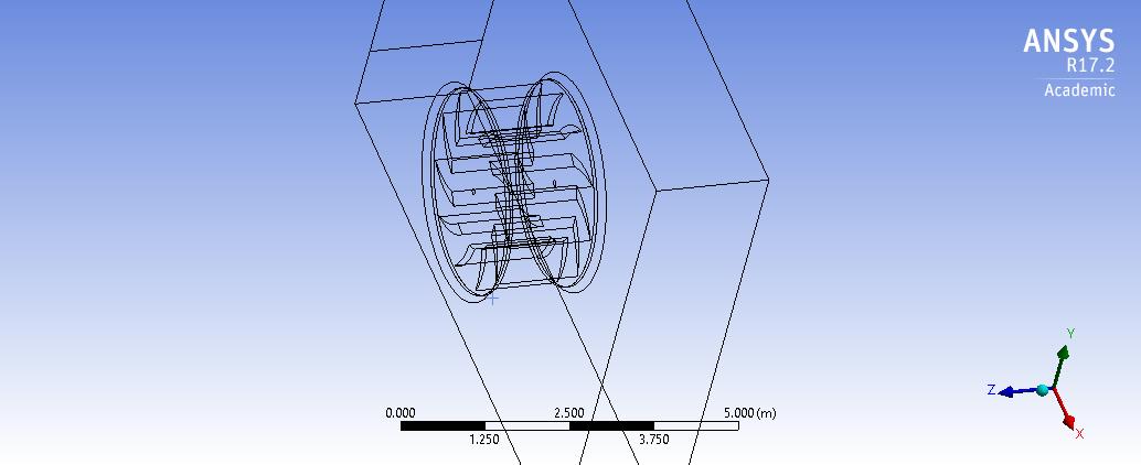
How to simulate 3D analysis of water flow(open-channel flow) for an undershot turbine.’ is closed to new replies.
-
3029
-
971
-
858
-
841
-
777
© 2025 Copyright ANSYS, Inc. All rights reserved.