-
-
November 7, 2024 at 5:10 am
M210098
SubscriberHi,
I am currently attempting a simulation tutorial by Ansys.
Link: https://innovationspace.ansys.com/courses/courses/structural-boundary-conditions/lessons/practice-quiz-and-simulation-exercise-5/quizzes/simulation-exercise-structural-boundary-conditions/
However, I am having difficulty setting the appropriate boundary conditions. From my knowledge, to enable the bracket to slide, compression-only support would be useful and to rotate the bracket, should I insert a remote displacement? As for a cylindrical support, in this question's context, it is not useful right? As the rigid shaft is not exactly having an effect on the bracket? May I clarify the above queries with you? Thank you.
-
November 7, 2024 at 7:36 am
Erik Kostson
Ansys EmployeeHi
’The steel bracket below has rigid shafts (purple) through holes A and B that fit snugly, where there
is no clearance, but the bracket can slide or rotate with the rigid shafts (cylindrical support – fix radial). Another shaft goes through
hole C (brown) and exerts a total of 10,000 N in the negative y-direction (remote force or like it says bearing load). Only the green bracket
will be analyzed in this simulation.'All the best
Erik
-
November 7, 2024 at 7:54 am
Erik Kostson
Ansys EmployeeHi
Also the supports cylindrical support – fix radial and frictionless are the same here so that is the hint for one question.
-
November 7, 2024 at 10:24 am
M210098
SubscriberHi,
I have tried out the methods which you have advised:
Compression-only Support for frictionless contact and Cylindrical Support (fix radial) and apply bearing load of 10000N in y-direction.
However, I am not able to obtain the total deformation of 0.06mm. May I just confirm if my steps are right? Thank you.
-
November 7, 2024 at 12:24 pm
Erik Kostson
Ansys EmployeeHi
It is a tricky one.
So as we said use frictionless support on A and B.
For the force it should be in neg., so - y direction (not pos.) .
Also it should be -5000 N (so half the force) since we use 1/2 symmetry :) - this is the tricky part.
With that we get the correct results.
All the bestErik
-
November 7, 2024 at 12:43 pm
M210098
SubscriberHi,
Sorry for the inconveinance again. If I only apply compression-only support (for frictionless contact), bearing load (-5000 in y direction) and cylindrical support (fix radial), I would end up arriving at the answer of only 0.2 mm instead. I had tried applying frictionless support instead but that resulted in a solver pivot error. May I clarify this with you again? Thank you.
-
November 7, 2024 at 12:45 pm
Erik Kostson
Ansys EmployeeHi
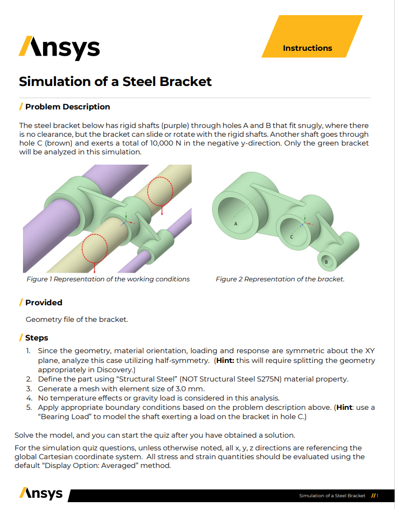
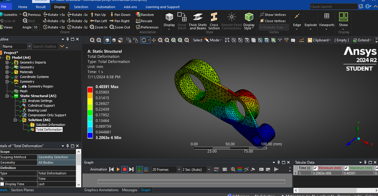
Do this since that works fine:
So as we said use frictionless support on A and B.
Sym.: Z in XY face (face that is on the sy. plane) as said in the pdf.
Use Structural Steel material,
For the force it should be in neg. y, so – y direction (not pos.) . Use components x=z=0, y=-5000 N for bearing load and not vector.
So the displacement should be down in – y (not up in pos. y)
With that we get the correct results.
All the bestErik
-
-
- You must be logged in to reply to this topic.
- The legend values are not changing.
- LPBF Simulation of dissimilar materials in ANSYS mechanical (Thermal Transient)
- Convergence error in modal analysis
- APDL, memory, solid
- How to model a bimodular material in Mechanical
- Meaning of the error
- Simulate a fan on the end of shaft
- Nonlinear load cases combinations
- Real Life Example of a non-symmetric eigenvalue problem
- How can the results of Pressures and Motions for all elements be obtained?
-
3882
-
1414
-
1241
-
1118
-
1015
© 2025 Copyright ANSYS, Inc. All rights reserved.