
-
-
December 28, 2021 at 7:30 am
navidMnzh
SubscriberHi! Wish u are having a nice day!
I'm working on a project which I need to set a remote displacement on a free standing remote point.
Here is the place where I need the point:
December 28, 2021 at 11:20 amAshish Khemka
Forum Moderator
How are you constraining the bodies on which thermal conditions are applied?
Regards Ashish Khemka
December 28, 2021 at 11:46 amSubscriberI do that in thermal analysis, by defining two Thermal Conditions.
One is 0 degrees and another is 10, and I apply each one to each surface.
Initial temperature is also 0.
December 28, 2021 at 3:28 pmpeteroznewman
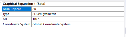
SubscriberIt looks like you have 1/2 symmetry for this model. Is the model fully axisymmetric? If so, you should do a 2D axisymmetric analysis, it will be much faster to get an accurate result.
If it is axisymmetric, but you want to stay in 3D, take another slice at 90 degrees and do a 1/4 symmetry model. That way you can put symmetry boundary conditions on both planes which will constrain 5 DOF on each body. All you need to prevent a pivot error is to constrain one vertex (or node) in one direction, the axis direction, on each body.
December 29, 2021 at 8:29 amSubscriberThanks for the help!
But the new question is, how am I supposed to turn this quadratic surface shape into a full sphere?
I did what you explained for me, made a 1/4 of the shape, and constrained two points in one direction:

 In the older shape, I used to use the symmetry option like below:
 and normally, this option now gives the the half of the sphere.
December 29, 2021 at 2:25 pmSubscriberOh! The geometry you started with a 2D surface, I assumed it was 3D, but now I take a closer look, I can see it is 2D.
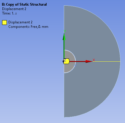
Since it is 2D, there is no need to add a constraint on a vertex for the third direction, since the model has no third direction!
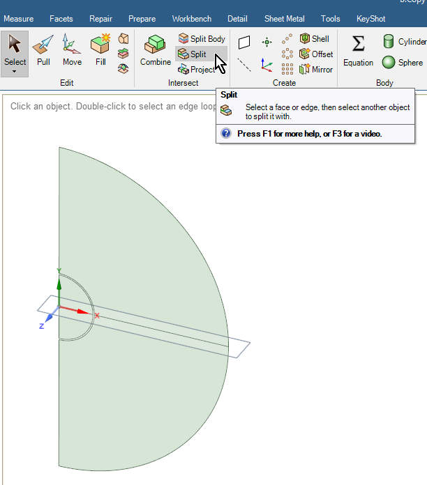
Since you want to do graphical expansion of an Axisymmetric model, you should keep the full axisymmetric geometry, just add a split that you can use to constrain the Y direction.
 In Mechanical, add a Y=0 to the two edges you created.
 December 30, 2021 at 7:00 amSubscriberThanks a lot sir!
I used the split edge option in designModeler and now I have fixed the system from the center.
Thanks for your help!
Viewing 6 reply threads- The topic ‘How to set a remote free standing point as fixed?’ is closed to new replies.
Innovation Space Trending discussions
 Top Contributors
-
peteroznewman
 5674
5674 -
scabo
 1890
1890 -
Dennis Chen
 1419
1419 -
javat33489
 1305
1305 -
Shyam Prasad V Atri
1021
Top Rated Tags
© 2026 Copyright ANSYS, Inc. All rights reserved.
Ansys does not support the usage of unauthorized Ansys software. Please visit www.ansys.com to obtain an official distribution.
-


The Ansys Learning Forum is a public forum. You are prohibited from providing (i) information that is confidential to You, your employer, or any third party, (ii) Personal Data or individually identifiable health information, (iii) any information that is U.S. Government Classified, Controlled Unclassified Information, International Traffic in Arms Regulators (ITAR) or Export Administration Regulators (EAR) controlled or otherwise have been determined by the United States Government or by a foreign government to require protection against unauthorized disclosure for reasons of national security, or (iv) topics or information restricted by the People's Republic of China data protection and privacy laws.
