Hello,
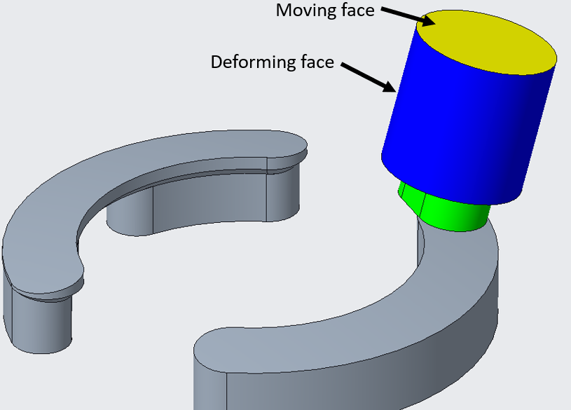
I am simulating a composite motion which consists of revolution and linear motion, details are shown in the following figures, as is shown in Figure 1 and 2, on one hand, the fluid 2 revolve around the Axis 1, on the other hand, the moving face which belongs to Fluid 2 move along the Axis 2, furthermore, there exits an angle α between axis 1 and axis 2, let’s say 5°(shown in Figure 3).
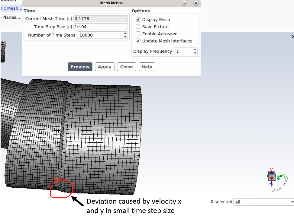
For revolution, I can use mesh motion or UDF(CG_MOTION) to realize it, but for linear motion, when I use the macro CG_MOTION, I need to decompose the linear velocity and then specify the velocity in x, y and z direction, it’s very complicated.
As is shown in Figure 4, I created a reference frame which on the axis 2 and its y axis coincide with axis 2, then I only need to specify the velocity of y direction, but how to set the linear motion in the new reference frame? Or is there any other simple way to achieve this motion?
Regards,
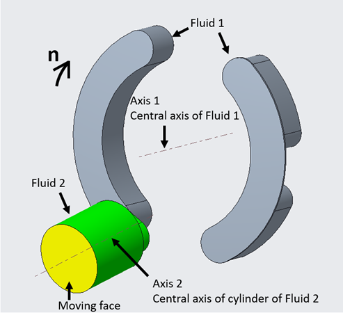
Figure 1
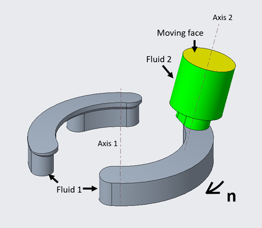
Figure 2
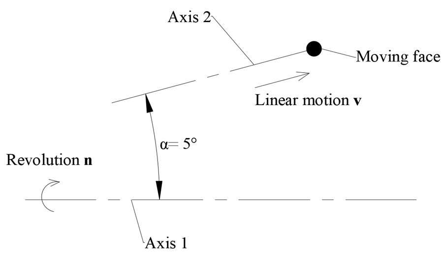
Figure 3
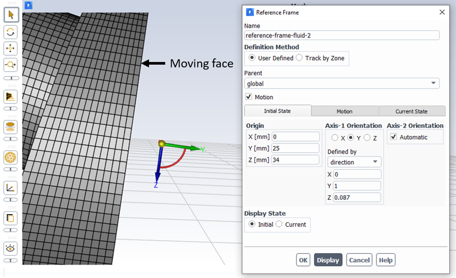
Figure 4